Proposal Bot/Spring/2020
Proposal Bot PCB Design
Author: Ethan Thiessa
Table of Contents
Introduction
This is the PCB design for our motor controller shield for Proposal Bot. This shield is designed with 4 stepper motor drivers, a buck converter, and a Bluetooth module. The purpose of this shield design is to control all four stepper motors with the motor controllers along with utilizing a buck converter to step down the 11.1V lithium ion battery, used to power the stepper motors, to 6V, so that we can power two servo motors used to control the ring box motion and up and down response of the pen plotter. This design also utilizes a Bluetooth module that can be used, so that the Proposal Bot movement can also be controlled using the Arxterra App.
Preliminary Circuit Diagram
Before I designed the PCB schematic, I laid out all the parts used in a simple circuit diagram to show how all the connections are made and what each component controls. Since the 3-Dot was not really feasible for Proposal Bot because of its size and the amount of motors that need to be controlled, an Arduino Uno is used to control the motor driver shield. Because the 3-dot wasn’t used, we have to incorporate a Bluetooth module, so that the arduino can communicate with the Arxterra app to control the motion of Proposal Bot. In order to add some complexity to the PCB design, we added a buck converter to take the 11.1V from the lithium ion battery and step it down to 6V to control the servo motors. The buck converter is used to get high current to the servo motors and to avoid using an extra power supply to power these motors.
PCB Schematic
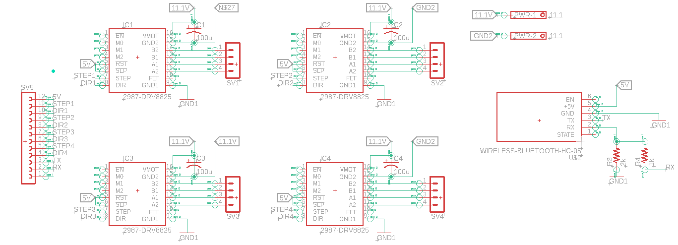
The first schematic is the Motor driver schematic utizlizing the Pololu DRV8825 motor driver carriers. the motor drivers’ main power is from the 11.1V lithium ion battery that is connected via the two terminal block labeled PWR-1 and PWR-2. The 11.1V power supply is connected to VMOT on the motor drivers, which is protected by 100uF capacitors. The RST and SLP connections on the motor driver are connected to a female header that will be connected to the arduino’s 5V power supply in order to power the logic in the motor drivers. The step and direction pins are also connected to the female headers in order for the arduino to connect to those headers to control the motors speed and direction. Finally the B2, B1, A1, and A2 pins are connected to a female header, so that the stepper motors can be easily connected to the motor drivers.
The buck converter utilizes a LM2596, a 3A step down voltage regulator in the surface mount package, to step down the 11.1V from the lithium ion battery to 6V. This step down is achieved from the voltage divider from R1 and R2 where R2 = R1{(Vout/Vref)-1}. The output of the buck converter is two 6v outputs that are connected to female headers for the servo motors to easily connect to. The buck converter is used in this design instead of a more simple linear regulator or another external power supply for a few reasons. Because we are using motor driver carriers that are easily connected using headers we had to add some complexity to our circuit design. For this reason we used a buck converter so that we can add intricacy to the design along with fulfill the design requirement of having a surface mount part. If we were to simplify the circuit, a linear regulator would be the better choice to conserve more space or another external power supply could be added to power the servo motors with the tradeoff of weight and size of Proposal Bot.


