DragonBot Maze Project Spring 2021
RFID Card Writing
Author/s: Matthew Hillsman
Table of Contents
Introduction
In order for our robot to be able to identify the card type using the RFID sensor, we needed a way to be able to write information onto the RFID tags, and later be able to read the written block of the card’s memory. Since there are a total of nine card types that the robot might run into while navigating the maze, a single byte is all that would be necessary to write to the card, and it can be written to the card with a value ranging from 0x01 to 0x09. In order to do this, code needed to be developed that could write this value to one of the memory blocks on the RFID card, and code also needed to be developed that could read this specific byte from the card’s memory. This code then needed to be tested for reliability and reading accuracy.
Writing to RFID Tag
For writing to the RFID card, this library was used. The starting point for the code was taken from the example of this same library titled ReadAndWrite.ino which can be found here.
This code was first tested before it was modified. The example was loaded into the Arduino Uno which was connected to the RFID breakout board via the SPI protocol. The information to be written to the device was left as it is shown in the example, and it was tested that the code wrote this information to the specified sector of the card.
After this initial testing of the example code was concluded to be successful, I decided to modify the code such there were no unnecessary code being performed and that it would only write the single byte that was necessary, and for it to write the information that I wanted it to.
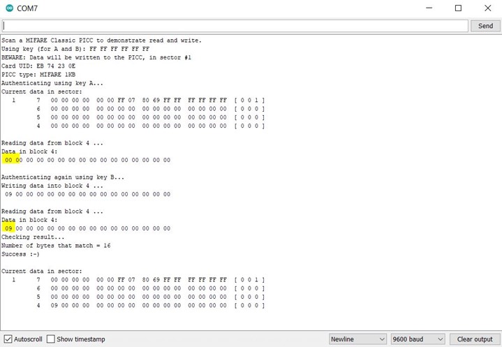
Figure 1 shows the serial output of the code that writes to the specified block. In this example I was writing 0x09, which indicates a treasure, to the desired block on the card. The data on the block before and after writing the byte is highlighted in figure 1.
Reading the Written Data
The code that reads the specific byte of data from the card was taken from the same example above, which was included with the library downloaded. In the example above, the code reads from the block that it had just written to in order to verify that the writing was successful. I took this part of the code, but I changed it so that it was not reading the whole sector of data, but only the byte desired, and removed all the unnecessary code that was unrelated to the reading of the specified byte.
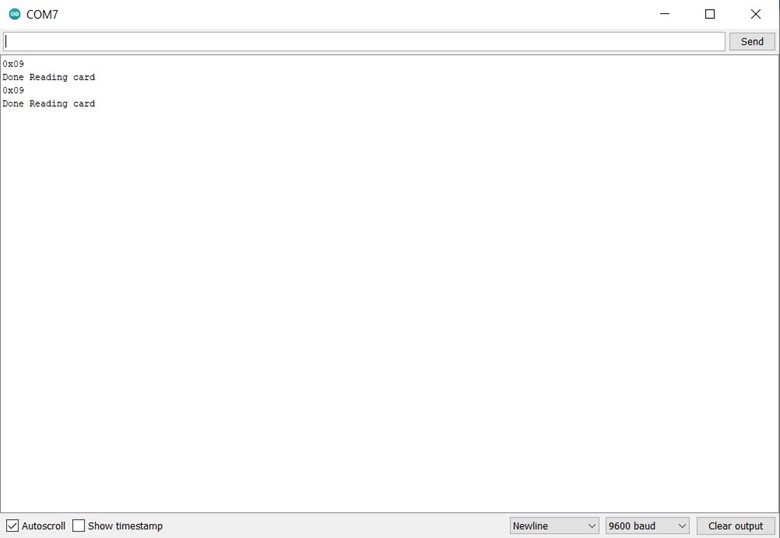
Figure 2 above shows the output on the serial monitor when I read the card that was written to in the example above. As can be seen, the byte that is being read is 0x09, which is the same value I wrote to the card above. From this output, it can be concluded that the code that performs the reading of the specified byte from the card was executed successfully.
I performed one final test to ensure that the robot will be able to use this information to differentiate between the card types. I added a green LED and a red LED to the breadboard and connected them to the Arduino uno. I wrote a couple of short lines of code, such that when a value of 0x09 is read, the green LED will turn on, when a card with a value other than 0x09 is read, the red LED will turn on.
As can be observed from figures 3 and 4 above, this test was a success and the LED turned green when the RFID sensor read a value of 0x09 from the card and turned the red LED on when a value of 0x00 was read.
Conclusion
In conclusion, the code that writes specific values to the specified block on the card’s memory and the code that reads this specific block were both developed and proved to be successful. This reading code was proven to be successful in giving the robot the ability of identification and differentiation of the card types.


