Rocker-Bogie Suspension System
By: Adolfo Jimenez (Manufacturing)
Verified By: Jordan Smallwood (Project Manager)
Approved by: Miguel Garcia (Quality Assurance)
Table of Contents
Introduction:
In order to mimic the suspension capabilities of the rovers sent to Mars by NASA, our rover will incorporate the same rocker bogie suspension system utilized by the Mars rovers to traverse an extreme desert-like terrain. This suspension system, introduced with the original Mars Pathfinder project, is the same design preferred by NASA for nearly all the Mars rovers. The main advantage of this type of suspension system is that the load on each wheel is nearly identical and thus allows an equal distribution of force regardless of wheel position. Taking into consideration the harsh terrain found on Mars this type of suspension system provides a better alternative to that of the common 4-wheel drive soft suspensions found on most automobiles.
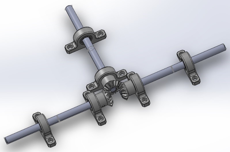
Figure 1: View of Differential Gearbox System without Box
Design enhancements:
For our project, since we are mainly building upon the design of previous semesters, we can utilize the things they did correctly and build upon things they may have overlooked. The main design difference, as it pertains to the suspension system, is the addition of a differential gear box. Whereas previous semesters utilized a barely functioning differential bar, or no differential at all, this semester we decided to remove the bar entirely and replace it with a much more functional differential gear box. This addition of a differential gear box will offset the wheel assemblies by about .8 Inches on each side and raise the main platform about .38 inches higher from the ground. Upon further research of rover suspension systems our group discovered a helpful blog on a website called Beatty Robotics. The website provides many helpful blogs describing the design and creation process for many custom Mars rovers and other robots. The particular blog post that helped us meet our needs pertained to a differential system used for a custom Spirit II Mars rover. Feedback on the blog pertaining to the parts used lead us to the website McMaster-Carr where we were able to order the parts to assemble our own Differential.
Suspension- Wheel Assembly:
Figure 2: Wheel Assembly
The wheel assemblies contain a total of 6 wheels with a symmetric build for both sides. Each side contains 3 wheels which are connected to each other by two links. The main linkage called the rocker has two joints, one affixed to an axel forming the differential mechanism and the other connected to the remaining two wheels. This linkage from the rocker to the other linkage between the two wheels is known as a bogie (hence the name rocker bogie). To go over an obstacle, the front wheel is forced against the obstacle by the center and rear wheels. The rotation of the front wheel then lifts the front of the vehicle up and over the obstacle. The middle wheel is then pressed and pulled against the obstacle by the rear and front wheels respectively until the wheel is lifted up and over the obstacle. Finally, the rear wheel is pulled over the obstacle by the front two wheels.
Suspension- Differential Gear Box:
Figure 3: Differential Gear Mechanism Close-up
The differential is composed of three identical beveled gears situated 90-degrees from each other at the center of the rover. Each gear is affixed to a 6-inch steel drive shaft that is mounted to the rover body by 2 mounted sleeve bearings. One gear connected to the left, one gear connected to the right, and the last gear assembled onto the main platform. The two rods facing opposite of each other on the left and right of the robot help serve as axels for the wheel assemblies. The axils are connected to the wheel assemblies by 2 parallel aluminum tubes that make up the rocker bogie suspension system. The inclusion of this differential insures that the robot’s body and pitch angle are always adapted even if one side of the rover steps over an obstacle. If one leg goes over an obstacle, an opposite force is applied to the other leg. So, if one leg goes up, the other leg goes down. This downward force onto the opposite leg helps the robot maintain traction in the leg assembly that is still on the ground. The way this works is when one side changes in pitch, say for instance one side begins climbing over an obstacle, this mechanism rotates the main body around the rocker joints by the average rotation angle of the two sides. For this differential mechanism, all gear ratios are the same. That means if the left gear rotates 10 degrees and the right gear rotates 20 degrees, the main platform will rotate 10 + 20 = 30/2 = 15 degrees or the averaged amount. This keeps the main box more level (less tilted) than it normally would be when going over large, uneven obstacles.
References:
- https://www.arxterra.com/2016-pathfinder-design-and-manufacturing-rocker-bogie-suspension-system-design/
- https://www.arxterra.com/news-and-events/members/pathfinder/pathfinder/pathfinder-generations/pathfinder-generation-4/
- https://en.wikipedia.org/wiki/Rocker-bogie
- http://citeseerx.ist.psu.edu/viewdoc/download?doi=10.1.1.538.6955&rep=rep1&type=pdf
- http://beatty-robotics.com/differential-for-mars-rover/
- https://www.mcmaster.com/


