
Spring 2017 Preliminary Design Document: Prosthetic Arm
The Robot Company | CEO Professor Gary Hill
Project Manager: Bianca Esquivel | Mission, Systems, and Test Engineer: Phuong Tran
Electronics and Control Engineer: Mikael Movsisyan | Design and Manufacturing Engineer: Cedric Yannick Mbetga
Table of Contents
Program Objectives/Mission Profile
by Bianca Esquivel – Project Manager
Problem Addressing | Program Objectives Statement and Mission Profile
Program Objectives:
There are over 1 million annual limb amputations every year around the world, which amounts to approximately one amputation every 30 seconds. Most amputations are caused by vascular diseases (54%), trauma (45%), and cancer (less than 2%). This generates a need for a product that we can provide: prosthetic limbs. Addressing the requirements of a customer that has suffered from trauma in their right arm just below the elbow, we have created objectives based on some of this individual’s preferred recreational activities. These objectives include creating a prosthetic arm that allows the customer to operate a computer mouse to play a game of minesweeper, pick up a cup of water to drink, and pick up a Chips Ahoy Cookie to eat.
Mission Profile:
Testing and final demonstrations for this product will be done by the customer, connecting directly onto their right arm with a strap around the bicep. The arm will not draw attention to itself visually or auditorily. As far as efficiency, the prosthetic arm will be able to help the customer use their prosthetic hand to operate a computer mouse, pick up a cup of water to drink, and pick up a Chips Ahoy Cookie to eat. The customer will not require the help of their left arm to operate their prosthetic arm.
Ref: Amputee Statistics
Project Requirements
by Phuong Tran – Mission, Systems, and Test Engineer and Bianca Esquivel – Project Manager
Program/Project L1 Requirements
Level 1 Requirements are considered High Level Requirements that are design independent. These requirements have been created in correspondence to the mission objective.
L1 Requirements
L1-1 Attachment – Project
The Prosthetic limb system shall attach to the user with zero hindrance of the elbow articulation.
L1-2 Integration – Project
Together, the hand and arm shall be able to perform 3 tasks: pick up a cup of water, pick up a Chips Ahoy cookie, and operate a computer mouse.
L1-3 Duration – Project
The Prosthetic Arm shall be able to operate for at least 16 minutes and 32 seconds, the longest duration allowed to play a game of minesweeper (999 seconds).
Ref: Minesweeper Info
L1-4 Safety – Project
The operating temperature of the prosthetic arm shall not exceed 50 degrees Celsius for safety reasons.
Ref: Safety Action
L1-5 Custom PCB – Project
The prosthetic arm shall implement a custom printed circuit board (PCB) that incorporates a complexity of design with dimensions that do not exceed 1.9” x 0.7” (48mm x 18mm), implementing at least 2 layers, and the use surface mount components.
Ref: Arduino Micro
L1-6 Mass – Project
The Prosthetic Arm shall be less than or equivalent to 1.83 kg (2.52% of Total Body Weight of 72.6kg)
L1-7 Length – Project
The prosthetic arm shall not exceed the length of 26 cm (User’s arm length – measured in class)
L1-8 Storage – Project
The project shall fit in one of Professor Hill’s room cabinets with maximum dimensions of 71cm x33cm x 39.5cm
L1-9 Cost – Program
The total cost of the prosthetic arm project shall be no more than $400 (USD)
Ref: Cost Report Arm
L1-10 Schedule – Program
The project shall be completed by the end of the Spring 2017 (May 20, 2017) academic semester for California State University, Long Beach
System/Subsystem L2 Requirements
Level 2 Requirements are lower level requirements that are design dependent. They must show trace-ability back to the L1 Requirements.

Design Innovation: Creativity Exercises
by Prosthetic Arm Group
Creativity Exercises
Our group completed four creativity exercises revolving around resolving one or two primary design problems. These methods of creativity were: BrainWriting (moderated by the Project Manager: Bianca Esquivel), Lateral Thinking (moderated by the MST Engineer Phuong Tran), Attribute Listing (moderated by Manufacturing Engineer: Cedric Yannick Mbetga), and Duncker Diagram (moderated by E&C Engineer Mikael Movsisyan).
Link to the Prosthetic Arm: Creativity Exercises PowerPoint Presentation:
System/Subsystem Design
by Phuong Tran – Mission, Systems,Test Engineer | Electronics and Control Engineer – Mikael Movsisyan | Cedric Yannick Mbetga – Manufacturing Engineer
Product Breakdown Structure
by Phuong Tran – Mission, Systems, and Test Engineer
The product breakdown structure (PBS) divides the system into subsystem based on the arm location and the components in that region. The arm structure consists of forearm, rotation joint, elbow, and upper arm. The EMG sensors are attached on the arm and calf externally to the arm structure; therefore, they belong in a distinct subsystem. Lastly, the miscellaneous subsystem reminds system engineer about cables, connectors, and bolts.
Rather than dividing the arm into 3D-printed, electrical, and mechanical subsystems, PBS divides the system into subsystem based on the arm location and the components in that region. This structure of the PBS aids the system engineer in visualizing the arm structure and the EMG subsystem. In addition, conops and intangibles become more obvious if the system engineer does not miss any component while visualizing.
PBS Diagram

Electronic System Design
by Mikael Movsisyan – Electronics and Control Engineer
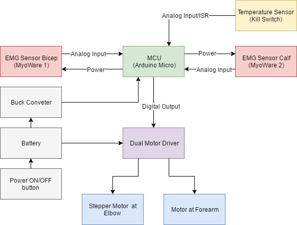
The system block diagram shows the signal flow between the Arduino Micro MCU and the different components to be used. The MCU will receive analog input from 2 EMG sensors and the temperature sensor. The MCU will implement a custom designed PCB as a shield. The digital output pins of the MCU will be used to communicate with a motor driver to control two motor actuators (one at elbow and one at forearm). A battery will be used to supply power to the shield and to the MCU, through a 5V Buck Converter. In turn the MCU will supply power to the sensors. An ON/OFF switch will be used to power the prosthetic arm up or down. The switch can be used as means to conserve battery energy or to act as a manual kill switch for the user.
System Block Diagram
Interface Definitions
by Mikael Movsisyan – Electronics and Control Engineer
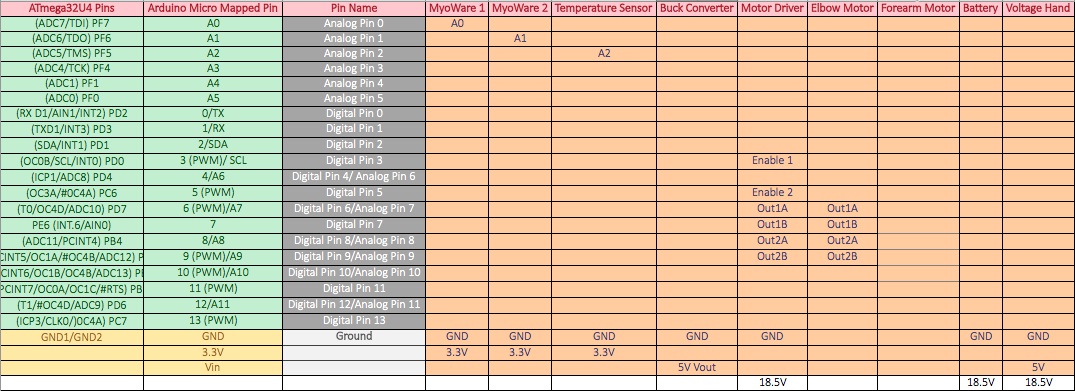
The interface matrix indicates the ATmega32U4 pin-outs that are allocated to sensor input and outputs to motor drivers and actuator motors. The matrix in addition shows which pins mapped on the Arduino Micro MCU board will be used for communication between components such as, and which ones are used for power supply lines.
Interface Defintions
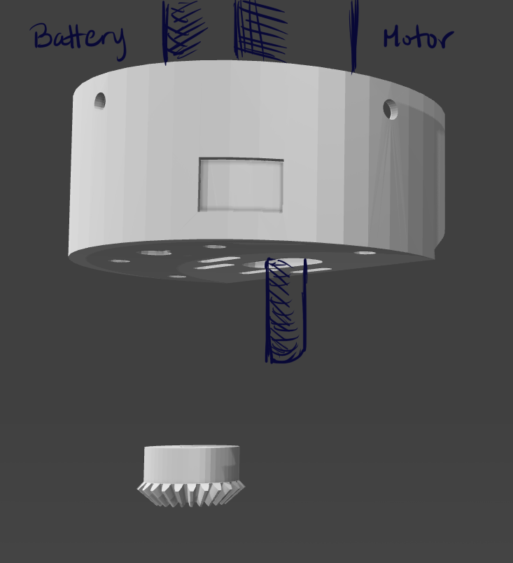
Mechanical Design
by Cedric Yannick Mbetga – Manufacturing Engineer

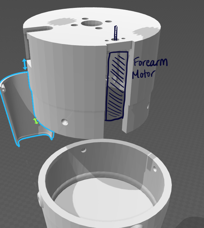
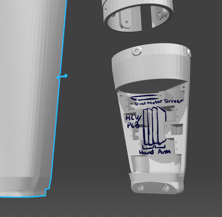
Above is a labeled, exploded view of the prosthetic arm body, rotation joints and gears to be reconstructed in SolidWorks. These components will be 3-D printed.
The images below show the placement of the electronic components within the arm body.
Design and Unique Task Descriptions
by Phuong Tran – Mission, Systems, and Test Engineer
Unique Tasks
According to the team research and L1, L2 requirements, a few near-future tasks were formulated to take the project forward. The tasks were specified according to the subsystem engineer and the requirement that triggers the need for the task.
| Subsystem | Requirement | Task | Schedule |
|---|---|---|---|
Mission, System & Test | L1.1 | – Meet with Prosthetic Hand to ensure proper mating of hand and arm – Realize a list of intangibles and more conops on the arm operation | 02.24-03.02 |
| Manufacturing | L1.2 L2.4.2 L1.5 | – Analyze Lachappelle’s Arm model in detail. (Especially, gear movement, gear placement, gear strength, and gear ratio) – Analyze the strength of PLA material for 3D print model – Study the strength of the motor torque – Test the torque of on-hand motor | 02.24-03.02 |
Electronic & Control | L2.2.1 L1.2 L1.1 | – Analyze the output of EMG sensor – Control motor with analog sensor input – Test stepper motor with feedback for specified angle rotation – Further improve the interface matrix | 02.24-03.02 |
| Project Manager | L1.6 L1.7 | – Create a tentative cost list of the components – Create a weekly project schedule in coordination with subsystem engineer | 02.24-03.02 |
Final References:
Most References were included intermittently in the blog post. Image reference is below: