Spring 2017 Prosthetic Arm: Servo Load Test
The Robot Company | CEO Professor Gary Hill
Blog Post created by Project Manager | Bianca Esquivel
Project Test Executed by Mission, Systems, and Test Engineer | Phuong Tran and Electronics and Control Engineer | Mikael Movsisyan
Table of Contents
Preliminary Information
Test Objective
During Con-ops of the prosthetic arm operation, we will rotate the wrist when the prosthetic arm is at the vertical orientation. The concern is if the servo can hold the weight AND rotate in the vertical orientation. This test is performed to clear up the uncertainty.
This experiment is performed in response to requirements
L1.2 – Together, the hand and arm shall be able to perform 3 tasks: pick up a cup of water, pick up a Chips Ahoy cookie, and operate a computer mouse
L2.2.1 – The prosthetic hand shall provide a 90 degree of rotation at the wrist. (forward and backward)
L2.2.4 – The motor at the wrist of the prosthetic arm shall have the torque rating of at least 0.03156 kg.cm
Problem: How much current will be drawn from the servo? Will the servo provide enough torque for rotation with load exerting on its shaft?
Materials
1-liter empty water bottle
Liquid water
Scale (increment at least 1g)
Fishing wires
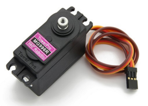
Servo MG996R
Arduino Uno
Digital Multimeter
Test Set Up
Step 1: Connect circuit to let the Arduino control the servo rotation with the multimeter measuring the current drawn
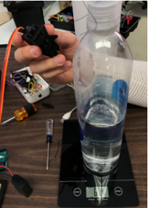
Step 2: Pour 100 mL of water into the bottle and weigh [Fig. 1]
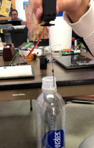
Step 3: Tie the water bottle to the shaft of the servo with fishing wires [Fig. 2]
Step 4: Command the Arduino to rotate the servo
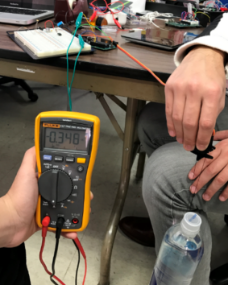
Step 5: Record the time the servo takes to complete one rotation and current drawn [Fig. 3]
Step 6: Repeat step 2 to 5 for 200 mL, 300 mL, 400 mL, 500 mL, 600 mL, 700 mL, 800 mL, 900 mL, and 1 L of water
Results
- Mass Tied to Servo Shaft (g)
- 0
- 104
- 201
- 301
- 399
- 500
- 604
- 702
- 805
- 903
- 1002
- Time (s)
- 5
- 5
- 5
- 5
- 5
- 5
- 5
- 5
- 5
- 5
- 5
- Current (A)
- 0.2
- 0.32
- 0.32
- 0.32
- 0.32
- 0.32
- 0.32
- 0.32
- 0.32
- 0.32
- 0.32
Conclusion
The servo MG996R can be incorporated in the prosthetic arm design because the servo can handle the weight AND rotate in the vertical orientation (point toward the ground). In addition, knowing how much current is drawn reduces uncertainty during power allocation.


