Spring 2017 Prosthetic Arm: Sleep ISR Test with Analog Sensor
The Robot Company | CEO Professor Gary Hill
Blog Post created by Project Manager | Bianca Esquivel
Project Test Executed by Mission, Systems, and Test Engineer | Phuong Tran and Electronics and Control Engineer | Mikael Movsisyan
Table of Contents
Preliminary Information
Test Objective
Purpose: The experiment is conducted to satisfy the L1.4 Requirement Safety – The operating temperature of the prosthetic arm shall not exceed 50oC for safety reasons and L2.4.1 Requirement – A temperature sensor shall shut down the MCU using an Interrupt Service Routine when the internal temperature of the arm exceeds 50oC.
Aim: Obtain Arduino code for sleep ISR to power down MCU. Modify code to receive input from an analog sensor (simulating a temperature sensor) and when the input value exceeds a threshold, initiate ISR to curb down current supply to the MCU.
Materials
Arduino UNO
Photoresistor
1k, 220 ohm Resistor
Multimeter
MG996R
Test Set Up
Procedure
- Set up a light-dependent voltage divider circuit with a photoresistor and the 1k resistor.
- Connect analog pin 0 of MCU to read the voltage drop across the photoresistor. Use this analog reading in place of using a temperature sensor, for ease of use.
- Connect Interrupt 0 (pin 2) to RX (pin 0) with a 220 ohm resistor.
- Obtain code for power down sleep ISR from Arduino Playground website.
- Connect servo to MCU.
- Modify code such that when the analog reading exceeds a threshold value, the sleep ISR will kick in.
- Modify code to sweep servo from 0 to 180 degrees.
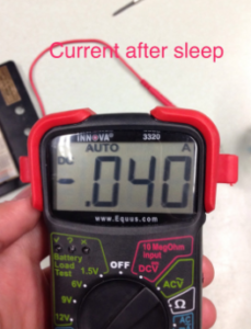
- Measure the current drawn from the battery before and after the sleep routine.
Results
The current readings from a 9V battery show that before sleep the MCU draws 0.376A and after sleep only 40mA. The servo PWM pin voltage drops from around 0.255V to 0V, as the servo turns off.
Conclusion
The sleep ISR significantly reduces current drawn from power source i.e. battery. This test confirms, that in the event of overheating, the LM34 temperature sensor reading will exceed the required threshold of 50oC thereby, powering the MCU down. The reduced current draw will cool down the PCB and the attached electronic components (e.g. servo).
Link to Code:
https://drive.google.com/open?id=0B6kkqAMmUffrSnEwSjlTWTBCODQ


