Spring 2017 Prosthetic Hand: Flex Sensor Test
The Robot Company | CEO Professor Gary Hill
Blog Post Created by Project Manager | Bianca Esquivel
Project Test Executed by Electronics & Control Engineer | Forest Nutter
Table of Contents
Preliminary Information
Test Objective
In order to sense different foot positions to control the prosthetic hand we chose to use flex sensors that are used to sense how much the user is bending their toes. This test is about me learning how to use the flex sensors, so we can verify that using flex sensors would work for our objective. We want these sensors to determine at the very least 5 different modes so we can use them to meet our requirements.
This Test Reflects the Requirement:
L2-4 Control | System
The hand shall be able to position the fingers to operate the computer mouse, pick up the cup of water, and pick up the chips ahoy cookie.
Subsystem:
L2-4.1 The control of the prosthetic hand’s fingers and thumb flexion and extension shall be controlled using flex sensors, which are connected to the each individual toe.
Materials
(1) Arduino Uno
(1) 10Kohm Resistor
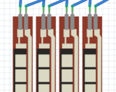
(1) 2.2″ Flex Sensor
(-) Wires
(-) Duct Tape
Test Set Up
A flex sensor is taped to the toe and hooked up to the Arduino Uno. The analog output readings can be monitored via the computer system connected to this simple testing circuit.
Arduino Code
Arduino Code:
SparkFun Inventor’s Kit for Arduino
Example sketch 09
FLEX SENSOR
In the previous sketch, we learned how to command a servo to
a new sensor, and use it to control the servo.
When the strip is straight, the coating will be a certain
get further apart, increasing the resistance. You can use this
animals, etc. See http://www.sparkfun.com/tutorials/270 for
Hardware connections:
The flex sensor is the plastic strip with black stripes.
The flex sensor has two pins, and since it’s a resistor,
Connect one of the pins to ANALOG IN pin 0 on the Arduino.
black orange) to GND.
Servo:
Because the cable ends in a socket, you can use jumper wires
jumper wires directly into the socket.
Connect the WHITE wire (signal) to digital pin 9
Note that servos can use a lot of power, which can cause your
servos or many of them, it’s best to provide them with their
http://www.arduino.cc/cgi-bin/yabb2/YaBB.pl?num=1239464763
with lots of help from the Arduino community.
Visit http://learn.sparkfun.com/products/2 for SIK information.
Version 2.0 6/2012 MDG
// Include the servo library to add servo-control functions:
// Create a servo “object”, called servo1. Each servo object
Servo servo1;
const int flexpin = 0;
{
Serial.begin(9600);
servo1.attach(9);
void loop()
int flexposition; // Input value from the analog pin.
// Read the position of the flex sensor (0 to 1023):
// Because the voltage divider circuit only returns a portion
// to the servo’s range of 0 to 180 degrees. The flex sensors
servoposition = map(flexposition, 400, 1023, 0, 180);
// Now we’ll command the servo to move to that position:
// Because every flex sensor has a slightly different resistance,
// output. To help tune our program, we’ll use the serial port to
Serial.print(“sensor: “);
// Note that all of the above lines are “print” except for the
// same line, then sends a final carriage return to move to
// After you upload the sketch, turn on the serial monitor
// You’ll be able to see the sensor values. Bend the flex sensor
// 600 and 900 in the map() function above, you’ll exactly match
// the flex sensor’s range with the servo’s range.
delay(20); // wait 20ms between servo updates
Results
The flex sensor detected an analog value of 773-777 of the foot at rest
The flex sensor detected an analog value of 795-805 of the foot raised/flexed
Conclusion
Their was a distinct difference between resting foot and raised foot but since the flex resistor was 2.2” it was not capturing the total flex of the foot. We plan to test a 4.5” flex sensor to see if we get better results. Since there was a distinct difference between resting foot and raised foot we should be able to use this type of sensor to control our prosthetic hand.
The image below is the fritzing diagram detailing how the flex sensors will be set up to interact with the motors of the prosthetic hand through wireless signals.


