Spring 2017 Prosthetic Hand: Mode Selector Test
The Robot Company | CEO Professor Gary Hill
Blog Post created by Project Manager | Bianca Esquivel
Project Test Executed by Electronics and Control Engineer | Forest Nutter
Table of Contents
Preliminary Information
Test Objective
In order to control the prosthetic hand we need to have different modes that will tell the hand to complete different tasks. Therefore, we need the mode selector to have enough modes for every task we need, as well as being reliable enough to not enter or exit the wrong mode. The tasks we want are gripping the hand, gripping the index finger, gripping the ring finger, going to open palm position, and toggling the thumb.
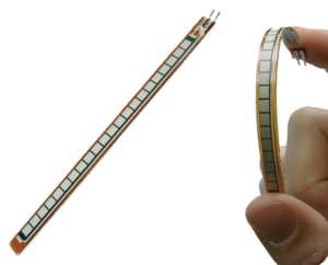
Our objective is to verify that the mode selector is working as intended. When all flex sensors are straight the mode=0. When all flex sensors are bent up, the mode=1, when left flex sensor is bent up, the mode=2, when right flex sensor is bent up, the mode=3 and when all flex sensors are bent down, the mode=4. The flex sensors that dictate the different modes were tested and are referenced in the Blog Post below.
This Test Reflects the Subsystem Requirements:
L2-4.1 The control of the prosthetic hand’s fingers and thumb flexion and extension shall be controlled using flex sensors, which are connected to the each individual toe.
L2-4.1.1 Different motions of the toes shall trigger individual movement in at least 2 fingers to control the left and right click of the computer mouse
Materials
(1) Arduino Nano
(2) Xbee
(4) Flex Resistors
(-) Wires
(-) Resistors
Test Set Up
The flex sensors are connected to the Arduino Nano, their flex conditions can then be tested in conjunction to the code to make sure that is outputs specific signals that can be programmed to activate the motors and the servo in the prosthetic hand in different ways.
Arduino Code
Arduino Code:
int AverageToes;
int LowToes=100; //Find Values through testing and customer feedback
int ErrorL=1.2;
Mode=0;
//Tuning ———-
//—————–
AverageToes=(FL1+FL2+FL3+FL4)/4; //Find average Toe flex
if (AverageToes>HighToes){ //Choose a Mode
PWM=(AverageToes-HighToes)*2;
else if (AverageToes
//if (LowTime>Time) { //Mode=4 Lower Toes
//Turn clock off
//else {
//SetClock
//}
else if (FL4>HighToes*ErrorR) {
PWM=FL4-HighToes*ErrorR;
else if (FL1>HighToes*ErrorL) {
PWM=FL1-HighToes*ErrorL;
else { //Turn clock off
PWM=map(PWM,0,7,0,255); //Scale the PWM based on the flex sensors. Values will require testing
}
Results
With some tuning for the thresholds of the modes we were able to get the mode selector to work for modes 0-4. We used mostly “if” statements that would check the average analog voltage and enter the mode for that value.
Mode=0 Flat foot
Mode=1 Raised toes
Mode=2 Right Toes raised
Mode=3 Left Toes raised
Mode=4 Toes lowered
Conclusion
The mode selector function will work, but it will require the threshold voltages to be tuned based on the flex sensor’s variation, the user’s foot shape and the foot movement. The mode selector should be able to control the hand by quickly reading the foot position then sending the mode to the hand to implement the motor movements based on what mode was entered.


