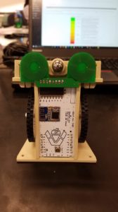
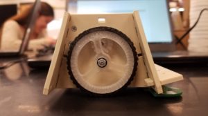
Sensor and Maze Summary Blog Post
Author/s: Alonso Quintero, Steven C. Tan
Verification: Steven C. Tan (Project Manager)
Approval: Steven C. Tan (Project Manager)
Table of Contents
Executive Summary
A new type of sensor will be developed to allow a robot to follow an invisible line to solve a maze.
Program and Project Objectives
Program Objectives
The Robot Company (TRC) will be debuting its 2019 line-up of toy robots and associated games at the Toy-Invasion 2019 convention in Burbank CA on January 6, 2019. Your team’s assignment is to make the 3D printed and/or laser-cut prototypes to be showcased at the convention, prior to production starting in the second quarter of 2019. The robots will feature our new ArxRobot smart phone application and the Arxterra internet applications allowing children to interact and play games around the world. In addition, the robots should be able operate autonomously in game mode. See game(s) (i.e, mission objectives) assigned to your robot by the Game Division. To decrease electronics cost, interoperability between all TRC robots will be maintained by incorporation of the 3DoT board, developed by our Electronics R&D Section. Modification of downloadable content is limited to software switch setting and robot unique graphics of the smart phone and Arxterra applications. Modifications of electronics is limited to custom 3DoT shields as required by the unique project objectives of your robot. The Marketing Division has set our target demographic as children between the ages of 7 and 13, with a median (target) age of 11. To decrease production costs, please keep robots as small as possible, consistent with our other objectives. As with all our products, all safety, environmental, and other applicable standards shall be met. Remember, all children, including the disabled are our most important stakeholders. Our Manufacturing Division has also asked me to remind you that Manufacturability and Repairability best practices must be followed.
Project Objectives
Create an adjustable grid layout game board, built by mass-produced puzzle pieces, where different game mats could be placed on top to allow various line-following robots to navigate through the board. Develop an accompanying custom sensor-shield which will allow the line-following robot to maintain its’ path on the puzzle layout. Completion by Monday, May 13th, 2019.
Mission Profile
Have the 3DoT PaperBot autonomously navigate through a maze using the shortest path, without straying away from the grid layout.
Requirements
Engineering Standards and Constraints
- The Maze and sensor shall be constrained to a cost not to exceed $250
Extensibility:
- The PaperBot shall contain a custom designed sensor-shield to interface with the 3DoT board v8 and future generations
- The custom sensor-shield shall be fabricated with Surface Mount Technology (SMT)
Maintainability:
- Disassemble and Reassemble of the robot shall be constrained to less than 20 minutes. The line-following robot shall be disassembled into PaperBot, sensor-shield, and 3Dot board within 10 minutes. The line-following robot shall be reassembled within 10 minutes; a functional test of the robot is conducted after reassembly to confirm its functionality.
- Disassemble and Reassemble of the game board shall be constrained to less than 20 minutes. The game board shall be disassembled into Maze Print, Corner piece, Male Edge piece, Female Edge piece, and Internal piece within 10 minutes. The game board shall be reassembled within 10 minutes; a functional test of the board is conducted after reassembly to confirm its functionality.
Schedule:
- The Maze and sensor shall be completed by the date of the final; Monday, May 13th, 2019
Social & Ethical:
Aesthetics:
- The robot shall be designed in such a way that there will be no dangling or exposed wires
Manufacturability:
Constructability:
- Constructability of 3DoT robot and game board shall be documented at the CDR and approved by the president of the TRC robot company.
Power:
- 3DoT PaperBot shall be provided by the 3.7V RCR123A battery included with the 3DoT board or use of the external battery 2.0mm PH series JST connector located on the 3DoT board. The RCR123A is a Lithium Polymer LiPo battery. All Safety regulations as defined in Section 4.3 Hazards and Failure Analysis of this document shall apply to the shipping, handling, storage, and disposal of LiPo batteries.
Environmental Health & Safety (EH&S) Standards:
- All standards, codes, and regulations as defined in the “Engineering Standards and Constraints” Section of this document shall apply to the Limbi.
- All Lithium (Li-ion, Li-polymer) batteries shall be purchased with and stored, when not in use, in a fire and explosion proof battery bag.
Functional:
- Software shall be written in the Arduino De facto Standard scripting language and/or using the GCC C++ programming language, which is implements the ISO C++ standard (ISO/IEC 14882:1998) published in 1998, and the 2011 and 2014 revisions. Required exceptions to this standard can be found here.
Review and show compliance with constraints on the project imposed by The Robot Company (i.e., CSULB) and Project Stakeholders. Specifically include University and applicable environmental, health, and safety standards and those safety standards specifically associated with the product (e.g., Children’s Toys).
Applicable Engineering Standards
Add material from the “Applicable Engineering Standards” section of the “Add material from the “Program Constraints” section of the “The System Engineering Method” lecture as applicable to your project here.” lecture as applicable to your project here.
Environmental, Health, and Safety (EH&S) Standards
Add material from the “Environmental, Health, and Safety (EH&S) Standards” section of the “Add material from the “Program Constraints” section of the “The System Engineering Method” lecture as applicable to your project here.” lecture as applicable to your project here.
Project Level 1 Functional Requirements
L1.1 The game board shall be made of modular pieces that can be assembled to any desired size
L1.2 The game board pieces shall be easily portable
L1.3 A game mat shall be created to fit on top of the game board
L1.4 Each modular piece of the game board shall have a hidden grid system built-in as requested by the customer
L1.5 The game board pieces shall be designed to allow a sensor-shield to follow the grid system and detect intersections
L1.6 The sensor-shield shall be designed to be used by a line-following robot
L1.7 The sensor-shield shall be designed to connect with a 3Dot Board
L1.8 The sensor-shield shall be designed to detect the hidden grid-system in the game board
L1.9 The line-following robot shall navigate through a predefined maze path based on the EE 346 maze
L1.10 The final product shall be completed and functional by May 13, 2019
System/Subsystem/Specifications Level 2 Requirements
L2.1a The assembled game board shall be in the shape of a square
L2.1b A game board piece shall take form of a corner, edge, or central piece to assemble the final shape
L2.1c Each individual piece shall be 233 mm X 233 mm with a male connector with a diameter of 65 mm
L2.1d The final game board shall be constructed in a 4 X 4 piece assembly
L2.1e The final size the game board shall be 1864 mm X 1864 mm
L2.2a All board pieces shall fit within a 14”X 14” uline box
L2.2b The total mass of the boards in the box shall meet OSHA weight constraints; weighing no more than 51 lbs
L2.3a The game mat shall be made out of cloth
L2.3b The EE346 maze shall be printed onto the cloth to fit the final size of the board
L2.4a The hidden grid layout shall be laid onto the board with a width of 25.4 mm
L2.4b Every intersection in the grid system shall lay center of the cells of the game mat
L2.4c Each cell of the game mat shall be 127 mm X 127 mm
L2.5a Copper tape of the same width shall be inlaid into the designated pathway
L2.6a The line-following robot shall be the 3DoT PaperBot robot
L2.7a The custom sensor-shield PCB shall be fabricated to be compatible with the 3DoT Board, as a forward shield
L2.7b The forward shield shall be designed using the 3DoT IR Forward shield as a template for the pinouts and profile shape
L2.8a If the inlaid material is copper tape, then the sensor-shield used shall be a dual coil metal detector PCB
L2.9a The 3DoT PaperBot with forward sensor-shield shall autonomously navigate through an enlarged EE346 maze
L2.9b A custom PID controller shall be implemented to maintain the PaperBot path
Provide a short summary of Derived Design dependent Level 2 Requirements. These level 2 requirements must provide links to the original level 1 design independent requirement(s) upon which they are “derived.”
Recommended subsections include: Mission, Systems, Electronics, Software (includes Firmware), Mechanical/Manufacturing, and Safety and Quality Assurance.
Allocated Requirements / System Resource Reports
| Component | Dimensions | Mass | Qty | Volume |
| Gatorboard | 233mmx233mmx12.7mm | 1.077kg | 64 | 0.04413 m^3 |
| Copper Tape | 12mmx50m | 0.204kg | 1 | 0.6m^2 |
| PCB | 78mmx29mmx2mm | 8.37e-3kg | 1 | 4.52e-6 m^3 |
| Maze Print | 932mmx932mm | 1 | 0.869 m^2 | |
| Uline Box | 355.6mmx355.6mmx355.6mm | .0315kg | 1 | 0.0449 m^3 |
| Total Mass | 1.281 kg | |||
| Total Volume |
Logically, the bulk of the volume and mass will come from the board pieces. These board pieces take up almost the volume of one Uline Uline box, leaving our margin for 0.0008m^3 therefore, multiple Uline boxes will be used to allow some contingency as well as leave enough room for the maze print.
| Resource | Expected Current Draw (mA) | Measured Current Draw (uA) | Uncertainty(%) | Margin(mA) |
| Induction Coil | 20mA | 0.22uA | 33% | 20mA |
The only power required is for the sensor’s which were found to use only about 0.22uA. The expected current draw for the project was 20mA meaning the project has a large contingency for unexpected current draw.
Project Report
Project WBS and PBS
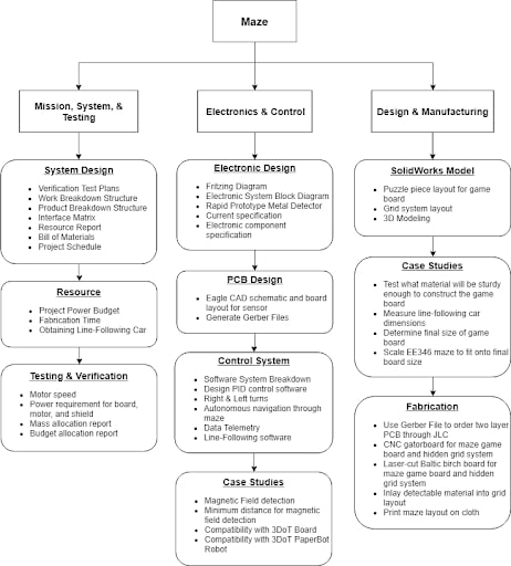
Product Breakdown Structure
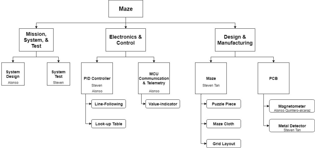
Work Breakdown Structure
Project Work Breakdown Structure (WBS) and Product Breakdown Structure (PBS).
For the most part, the way the project and work was broken down was as follows. the Manufacturing aspect, such as the design and manufacturing of the board, PCB, and maze cloth were handled by the project manager. The parts that had to do with controlling, and reading the sensor as well as utilizing it for line following and assisting in maze solving was done by the MST with some assistance from the Project manager.
References:
- Chapter 4, section 3 of the NASA Systems Engineering Handbook titled “Logical Decomposition” includes a section that briefly covers the Product Breakdown Structure (PBS.) Chapter 6, section 1 titled “Technical Planning” includes a section that explains the relationship between the Work Breakdown Structure (WBS) and the PBS. The PBS is the responsibility of the systems engineer. There is not quite enough information between these two sections to create a long presentation; instead focus on first going over the info, and then work with your division members to create an example PBS during the meeting.
- NASA SE Handbook Sections 4.2, 4.3-2, 6.1-4/5,G-1
- Arxterra / Classes / Engineering Method, select
 tab, scroll down to The Robot Company Work Breakdown Schedule.
 - WBS and PBS PowerPoint by Avi Sharma
Cost
| Components | Description | Source | List Price | Quantity | Expected Cost | Uncertainty | Margin | Actual Cost |
| Gator Board | 18 X 24 X 1/2 in. | Amazon | $27.99 | 12 | $335.88 | 33% | $110.84 | Provided |
| Copper Tape | 50 m X 12.7 mm | Amazon | $22.95 | 2 | $45.90 | N/A | N/A | $45.90 |
| CNC | 3dhubs | $15.00 | 64 | $60.00 | N/A | N/A | Provided | |
| Shield | JLCPCB | $4.00 | 15 | $67.96 | N/A | N/A | $33.34 | |
| Resistor | 220 ohm 0402 | Arrow | $0.0025 | 20 | $1.50 | 97% | -$1.45 | $1.50 |
| Zener Diode | 1N4148 0402 | Arrow | $0.1425 | 20 | $1.70 | 44% | $0.75 | $1.70 |
| Capacitor | 10nF 0402 | Arrow | $0.076 | 20 | $1.52 | 23% | $0.97 | $0.79 |
| Maze Print | Signs | $53.23 | 1 | Provided | ||||
| Allocated | $514.46 | $111.11 | $100.00 | |||||
| Expected | $83.23 |
The biggest cost came mostly from the fabrication of the boards simply due to the nature and size of the boards. The sensor shield did not bring too much of a cost aside from the multiple iterations that were done in redesigning the sensor.
Schedule
Burndown and/or Percent Complete
The project burn down is broken up into how many tasks we had to get down from the beginning of the semester to the end (16 weeks) ideally. One task would get done per week, but in actuality several of the tasks would not be completed for 2-4 weeks. It is because of this delay that we are currently projected to be 64.3% done with the final project
Concept and Preliminary Design
The Concept is to have a line following robot that can follow a hidden metal grid. The grid could be used as a guide to allow a robot to solve mazes or be a piece in a game.
Literature Review
EE444 Lecture 12 ADC was used in the creation of the sensor reading code. The lecture outlines the basics of the ADC in how it functions, how it is built, and how to modify its behavior. Initially the sensor was read using a free-running ADC. The free-running ADC, however, proved to be an issue as it was reading the sensors as they were still being charged and introducing noise. The final design, still used the concept of the free-running ADC in that the ADC interrupted the program when it finished a conversion. the new design, however, starts the ADC when the sensor is done charging in order to control what is being read.
Provide theoretical background, concepts involved in the design process and a summary of the key literature and online resources (e.g. Arxterra – Project Summary Post) that has been researched and used in the design effort. A summary of similar previous designs can also be discussed to show strength and weakness of your design compared to others.
Design Innovation
Maze Game Board:
- Four unique compatible puzzle pieces allow for the game board to be portable and assembled in any desired shape and size.
- Corner
- Male Edge
- Female Edge
- Internal
- A copper tape grid system will be laid onto the boards, allowing multiple game designs to be utilized.
Game Board Mat:
- A cloth print of the maze to hide the grid system.
Sensor-Shield:
- Two induction coils to detect the invisible grid system inlaid onto the game board.
Conceptual Design / Proposed Solution
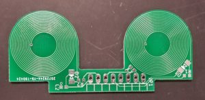
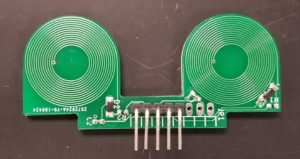
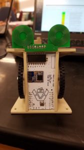
The robot would detect the hidden grid using a metal sensor composed of 2 coils acting as inductors detecting the metal underneath.
System Design / Final Design and Results
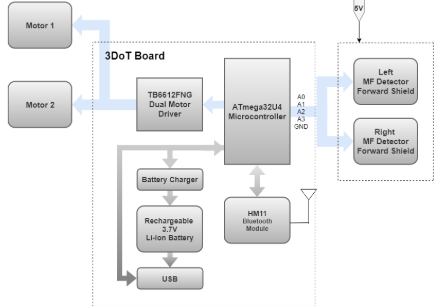
The final design was a metal sensor composed of 2 coils acting as inductors. the coils produce a current and voltage when in proximity with metal which can be read by the arduino. this allows the robot to know if it is over the metal line or not.
System Block Diagram
Interface Definition
| 3DoT Board | Magnetic Field Sensor-Shield |
| A0 | Din1 |
| A1 | DOut1 |
| A2 | DIn2 |
| A3 | DOut2 |
| GND | GND |
Modeling/Experimental Results
Some of the experimental results that were found were that the sensors have a wide enough range of values to be able to implement a decent proportional control for the motors. The motors do have to be run past a at least a PWM value of 75 in order for the robot to not get stuck.
Through some experimental testing, it was found that the sensor becomes saturated after 100 pulses with a period of 20us and a duty cycle of 50%. this is useful because it showed what conditions will provide the best resolution as well as what the minimum amount of time is required for the sensor to be powered. Now only about 3ms are used on powering and reading the sensors allowing for faster response times from the robot.
Electronic Design
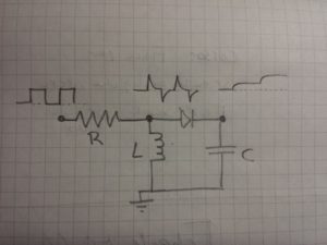
https://www.instructables.com/id/Simple-Arduino-Metal-Detector/
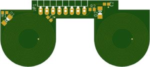
In Eagle a flat spiral coil is created to act as the induction coil. A voltage is pulsed into both the A0 & A2 pin, these pulses charge the inductor which will gradually change from an open circuit to a closed circuit. This alternating charged and discharged voltage waveform goes into the diode and only the positive phase of the peaks are outputted from the diode. Those peaks then gradually charge the capacitor.
When metal is placed in the center of the coil the inductance of the coil is then reduced, thus reducing the peak voltage across the diode and reducing the charge of the capacitor.
PCB Design
Firmware
The code will read the sensors and then control the motors depending on the values of the sensors. The sensors are pulsed with 100 pulses at 10us each pulse. The pulsing of the sensors is staggered in such a way that the conversion for one sensor can be started while the second sensor is still being powered. By the time the second one is done pulsing the first coil will be done converting and the second coil can begin. The conversions are sent to the ADC and the code is interrupted when it is complete.
void pulsesen(){
  /*Pulses Sensor 1 first for 50% of the pulses
   * then it pulses the second sensor and the first at the same
   * time and then takes the reading of the first sensor.
   * then it pulses the second sensor. and reads second sensor at the end.
   */
  for (int ipulse = 0; ipulse < npulse*1.5; ipulse++) {
    if(ipulse=npulse*0.5 && ipulsenpulse){
      digitalWrite(pulses[1],HIGH); //takes 3.5 microseconds
      delayMicroseconds(inttime);
      digitalWrite(pulses[1],LOW);
     delayMicroseconds(inttime);
    }
  }
  ADMUX &= B11100000; // clears the pins
  ADMUX |= sen[1]; // sets the pin
  ADCSRA |= B01000000; // starts the conversion
  delayMicroseconds(40);
  pinMode(caps[1],OUTPUT);
  digitalWrite(caps[1],LOW);
  delayMicroseconds(20);
  pinMode(caps[1],INPUT);
}

The bot will then use the average and a set threshold to determine an error
if the error is above a certain point, it will speed up the appropriate wheel in order to stay on course.

pulsesen(); //pulses the sensors and begins readings
int rightSensor = threshold2-average2; //compares to threshold
int leftSensor = threshold-average;
if (leftSensor > 0){
  set_right_speed(50);
  Serial.println("Turning Right");
}
else{
  set_right_speed(40);
}
if (rightSensor > 0){
  set_left_speed(50);
  Serial.println("Turning Left");
}
else{
  set_left_speed(40);
}
Mechanical/Hardware Design

Corner Piece

Female Edge Piece

Internal Piece

Male Edge Piece
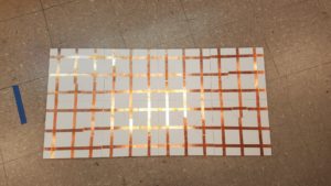
Prototype (Corner, Male Edge, Female Edge)
Verification & Validation Test Plan
| Level 1 Requirement | Test instruction | Pass/Fail | Pass condition |
| L1.1 | Create a board layout that resemble a “+” sign using only 5 pieces then count how many pieces have only one other piece connected to it | 4 pieces | |
| L1.2 | Assemble the board pieces in less than 10 minutes | 0-10 min | |
| L1.2 | Disassemble the board pieces in less than 10 minutes | 0-10 min | |
| L1.1 | Create a board layout the resemble a “-” sign by placing one puzzle piece down on the floor and then placing 2 more pieces on opposite sides of the first piece. then count how many pieces have only one piece connected to it | 2 pieces | |
| L1.1 | Add to the previous layout to create a square, then count how many ieces have less than 2 pieces connected to it | 0 pieces | |
| L1.4 | have the customer slide a finger from one corner of a piece to any opposite corner and count the number of tape the finger slides over. | any integer greater than 0 | |
| L1.5 | Place the bot on the board an allow it to run, then count how many times the bot stops at an intersection | any integer greater than 0 | |
| L1.8 | Place on a cruved track and observe if the bot veers off course. | Fail if the bot does not follow the line | |
| L1.6 | Place a line following robot at the center of an intersection and count how many intersections the robot is overlapping | 1 | |
| L1.7 | connect the sensor shield to a 3DoT board and count how many pins did not fit in an I/O port of the 3DoT board | 0 | |
| L1.6 | Connect the sensor to a line following robot and count up to 5 seconds and record how many seconds the sensor stayed on the line following robot without falling down | 5 seconds | |
| L1.3 | Place the mat on top of the board and measure how much of the mat is hanging off the board | less than 12.7mm | |
| L1.9 | Place the bot at the start of the maze and observe if the bot reaches the end of the maze and stops. | The robot reached the end of the path | |
| L1.10 | The tests were done on or before 05/13/19 |
Concluding Thoughts and Future Work
Improvements that could definitely be made to these sensors and code is a better PID calculation to have the robot follow the metal lines smoother as well as slightly more sensitive sensors. Some lessons learned in the production of this code were to structure the code better to make debugging easier and not to write too much code at one time without testing along the way. If I could go back in time I would start with smaller steps and make sure I improve the readability of the code from the start.
To improve on the overall assembly and disassembly of the game board, the diameter of the male connector of the puzzle piece would have to be slightly smaller than that of the female connector of the piece. This should be done to reduce the friction of the boards which would improve the speed of the assembly and disassembly, and it would make the boards connect flush with one another. Some lessons learned in the fabrication of the game boards were to assemble the game board in its entirety and measure and draw the grid layout multiple times to ensure absolute accuracy prior to laying down the copper tape.
References/Resources
These are the starting resource files for the next generation of robots. All documentation shall be uploaded, linked to, and archived in to the Arxterra Google Drive. The “Resource” section includes links to the following material.
- Project Video YouTube
- CDR
- PDR
- Verification and Validation Plan
- SolidWorks File
Loading...
- EagleCAD File
Loading...
- Arduino
Loading...
- BOM


