Sojourner Spring 2020
Sensorless Encoding Trade off Study
Author: David Garcia
Verification: Robert Pearson
Approval: Chris Hirunthanakorn
Table of Contents
Methods of RPM Estimation
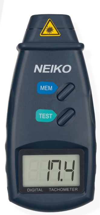
Heading into this project we had to devise various ways to get RPM data as well a way to create a value assumed to be “true”. This “true” value was taken to be an external tachometer. This will give us a way to have a common variable between each method of calculating RPM data.
Figure 1 – Neiko Tachometer
Encoders
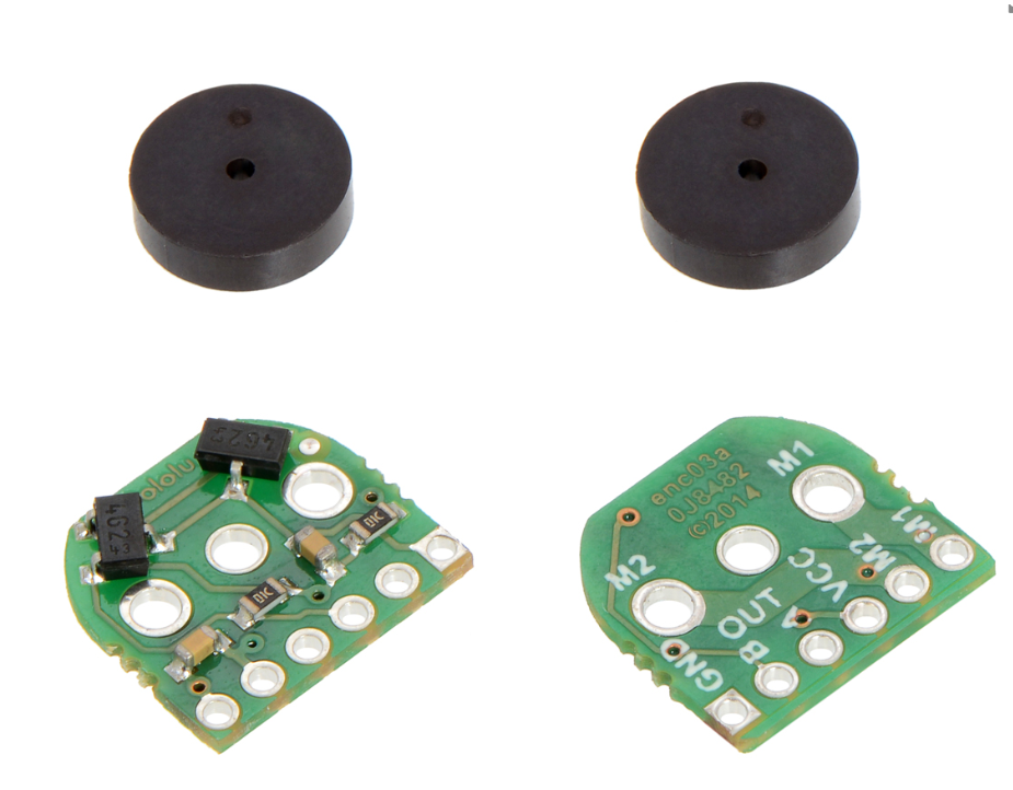
The first and most straightforward part was to get the encoders working with the motors we bought.
Figure 2 – Pololu Magnetic Encoder
While these encoders were utilized in previous Sojourner robots, each team also complained of the trouble with fitting the wires during construction.
The way these encoders work is by connecting to the A and/or B lines which will generate a pulse at a rate of 12 per revolution. Using the know gear ratio of the motor and this we have come up with a constant to allow for accurate RPM values.
The spring 2019 class had actually already written some code for using the encoders we were planning on using. It was written for a fully built Sojourner but we only needed to have a single motor for testing.
There are only three variables needed to find RPM Data from the encoders. One variable is needed to for incrementing ticks, one variable is need to compare. If you increment the variable on each pulse of the encoder then and compare it in a loop that repeats at a known time you can know how often the shaft rotated in the time between loops.
Commutator Noise Circuit
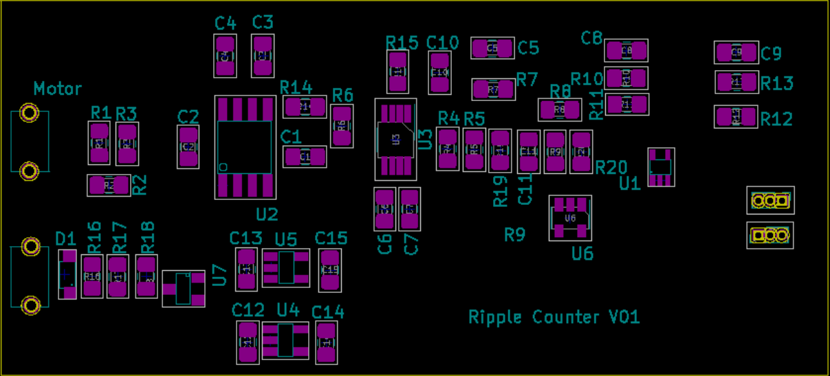
This circuit was based upon translating Commutator Spikes into a frequency that relates to the RPM of the at the motor Shaft. A major advantage over this method would the elimination of all the wires that would have to be connected at the motors. A major disadvantage of how we wanted to do this method would be using polling versus interrupts.
Back EMF Circuit
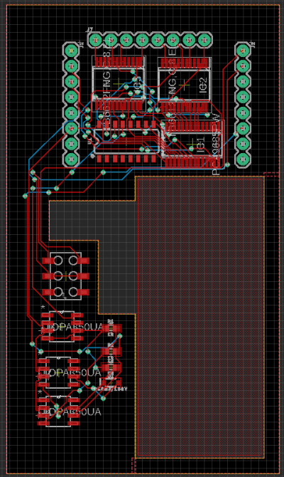
The accuracy of the BEMF circuit was largely related to the ability of our delay to accurately avoid reading the initial exaggerated sparks at the start and the ability of the our circular buffer to be large enough to average properly.
Figure 3 – Back EMF Circuit
Methodology
As stated before, each mode was to be tested against the tachometer over a the same range of analog write values starting from 15 and going to 255, as that would be the max value of the analog write function. At each value a reading from the tachometer and the estimate would be taken. The last thing would be to calculate a total percentage off from the readings.
Costs
Comparisons
We were unable to perform a true examination of our methods
Implementation
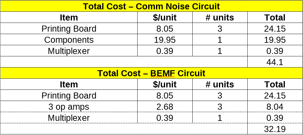
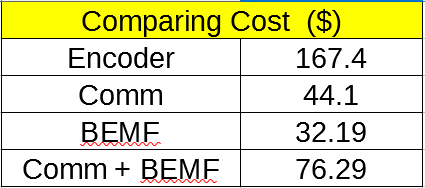
Even by implementing both Back EMF and comm noise we are able to significantly reduce the price of the project.
Conclusion
Just as we were starting to get to the point of having all the circuits working we ran out of time and were unable to do the entire trade off study to compare the methods in a systematic way. What we did see was a promising for our results. Irregardless, either method has a vast cost saving over the encoders being used.
The encoders themselves cost around $9, but they only function with the extended shaft motors which cost around $18. The hybrid-implementation of sensor-less encoding would be cheaper as the price per unit on a single board is $8.05, and they can be implemented without the costly extended shaft motors. Taking them together would still result in savings of $91.11.

