Goliath Fall 2016
Simulation and Experiment of 3D Printing
By: Dylan Hong (Design and Manufacturing Engineer)
Approved by Kristen Oduca (Project Manager)
Table of Contents
Computer Simulation
3D Model
After creating a preliminary design sketch and determining the dimensions, I created a 3D model of the Goliath using Solidworks as shown in Figure 1 .
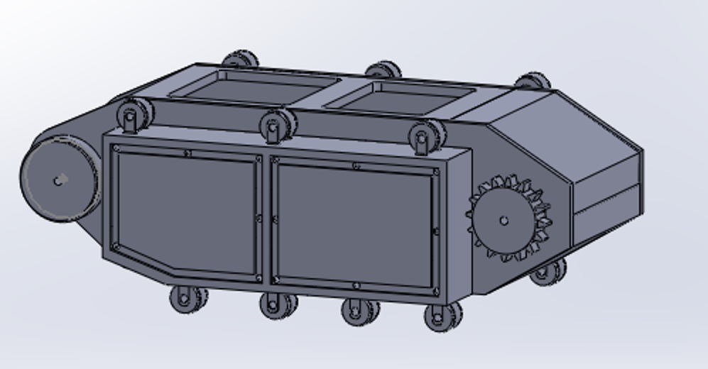
Figure 1 – 3D Model of Goliath Side View
For the body, I created five parts: the side panel, side box panel, and top panel with doors, top panel with hinged doors, and the bottom panel as shown in Figure 2 from a top view angle.
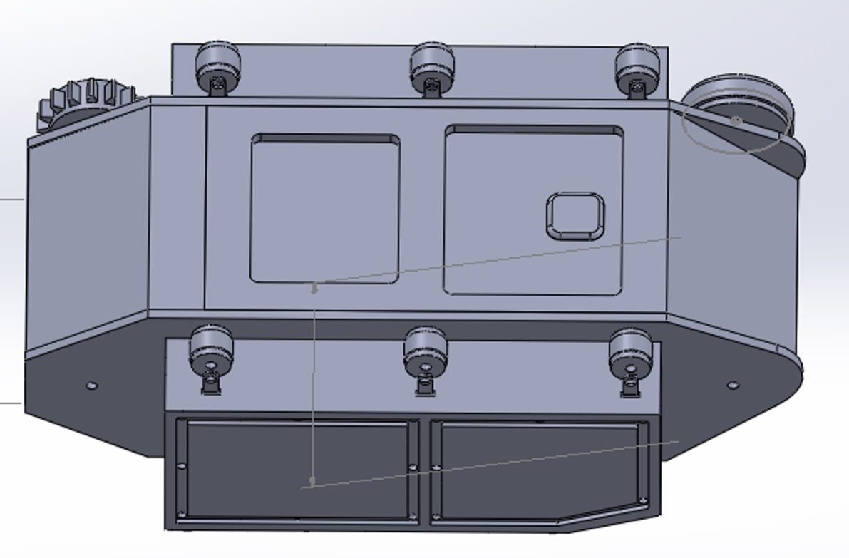
Figure 2 – 3D Model of Goliath Top View
The side panel consist of two holes made for the shafts of the drive and large road wheels. The side box includes seven road wheel holders and will be attached to the side box with screws and bolts. The top panel with doors were created to support the smartphone’s camera and periscope. The top panel with hinged doors will be connected to the top panel with doors and will act as hinged door that will open upwards to insert the smartphone and access the components of the 3DOT board and PCB board.
For the sub components of the body, I modeled the wheels and the smartphone. There were three different wheel types: the drive wheel, the large road wheel, and the small road wheel. The drive wheels are connected to the motors and will be used to rotate the tracks and the other wheels. The large road wheels also moves the tracks but will not be connected to the motors. The small road wheels will be connected to the side box holders and will rotate with the tracks. The smartphone model was created to display the fitting of the phone within the body and its camera’s position in conjunction with the opening doors of the top panel. The camera of the phone must be within the opening of the doors so that the periscope can be placed upon the lens to broadcast our live feed.
3D Print Time
Now that we 3D modeled the Goliath, I was able to work with my division manager to find out the 3D print time of our model with the use of the Makerbot software. We determined the settings of the printer to be at standard quality with a layer height of 0.20mm, 20% infill, raft, and 3 shells shown in Figure 3.

The material we used was PLA with an extruder temperature of 230 degrees Celsius. With these settings, our total print time of the Goliath body was estimated at about 22 hours shown in Figure 4.

The 22 hour print time exceeded the level one requirement of all components being printed need to be printed in a six hour period.
The Makerbot software also assisted us in finding an error with the side panel and side box of our model, in which Solidworks was unable to detect. The width of the side box dimensions was not long enough and would have brought difficulties when connecting the parts together as shown in Figure 5.
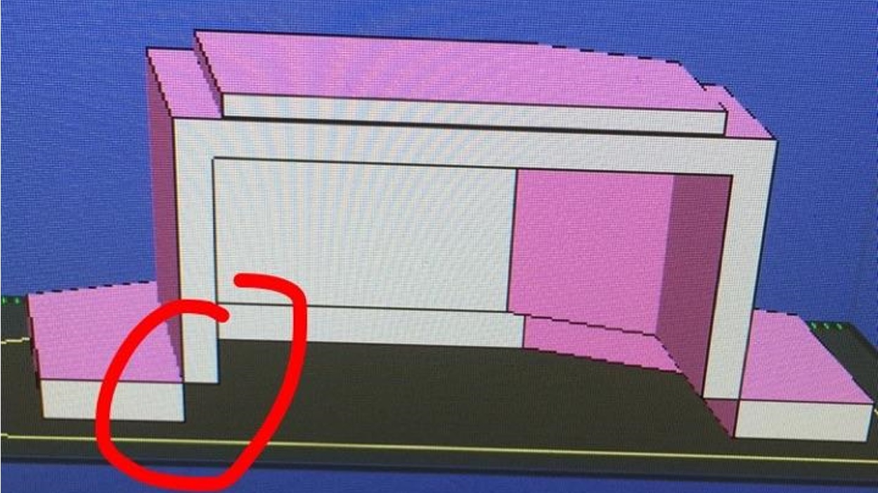
This led to the remodeling of the side box, which resulted in an easy fix of increasing the width of the box by 0.25 inches.
Model
3D Printing
We 3D printed only the side box just to see how it would come out since it was our most difficult part as shown in Figure 6.
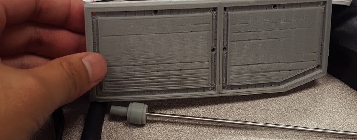
The printed side box was sturdy but lacked details because of the amount of infill used, which was 20%. As infill increases, print time and detail will too.
Conclusion
Overall, our initial design met most of the level one and level two requirements except for the print time requirement with a total of six hours and two hours per part. Also, upon meeting with the customer in regards to our design, he suggested that we make our final product as small as possible, where the components were tightly fitted. This meant that we had to change the scaling of our design and that the smartphone must be removed from the body and replaced onto the top panel of the Goliath.