Sojourner Spring 2020
Sojourner Building Instructions
Author: Alex Dalton
Verification: Robert Pearson
Approval: Chris Hirunthanakorn
Table of Contents
The 4 Main Parts of Sojourner
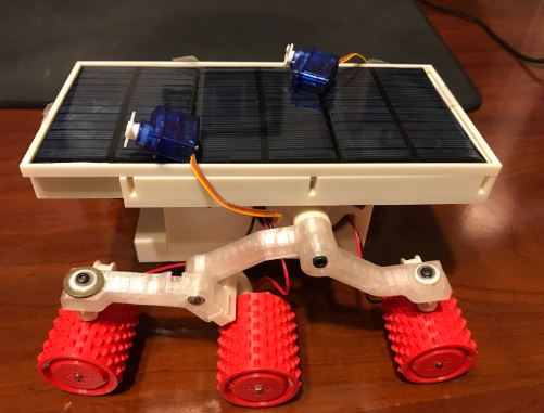
The four main parts of Sojourner are the rocker bogie, phone holder, solar tray, and main chasis. The rocker bogie attaches the wheels to our main chasis and keep our robot running when going over more difficult terrain. The phone holder is on top of the main chasis and positions the phone so that video can be streamed to the control panel. The solar tray is on top of the phone holder and keeps the solar panels in place. The main chasis contains the 3DoT board and has a gearbox that keeps the rocker bogie legs aligned. These parts are 3D printed from fusion 360, which lets us view the 3D models. Changes to any of these need to be made in a software like solidworks.
Rocker Bogie
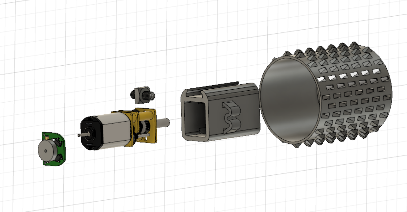
Figure 1: The wheel
The shaft of the motor should securely fit into the wheel and the nut and screw should keep the motor securely in the wheel. The motor mount connector should then slide into the motor mount and a 6mm alignment pin should be used to hold it in place.
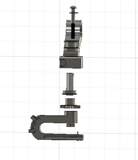
Figure 2: The wheel mount
The motor mount connector is screwed into the rocker bogie with the following parts to keep it in place. The gear is used to connect with the servo gear for servo based steering as the servo moves the mounted wheel. The servo mount will then slot into the rocker bogie leg and be screwed in. Keep in mind the size of the servos you plan to use, the servo mount will likely need to be redesigned to accommodate them.
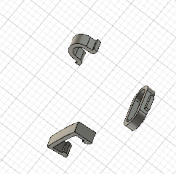
Figure 3: The wire holders
These three smaller parts clip onto the legs of the rocker bogie and are used to keep the wires in place.
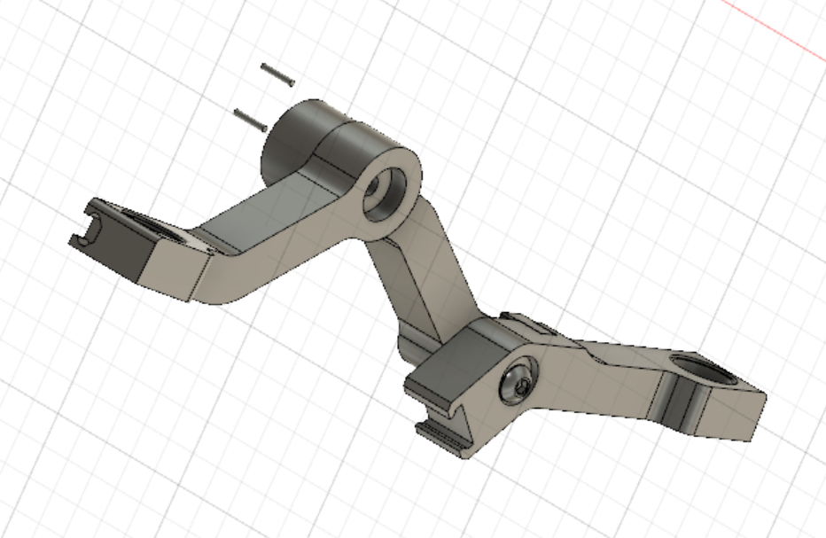
Figure 4: The rocker bogie legs
The last part of the rocker bogie is connecting the legs together as shown the 2 alignment pins are placed to keep the upper parts of the legs together. A screw is placed through this part of the rocker bogie that will be discussed in the chasis section. The lower leg is connected with a screw and a nut at the end to keep it in place. This lower leg is connected to two wheels. The one at the end is assembled the same as the previous wheel and the middle wheel’s servo mount connector slides into place.
Phone Cradle
Figure 5: The phone holder
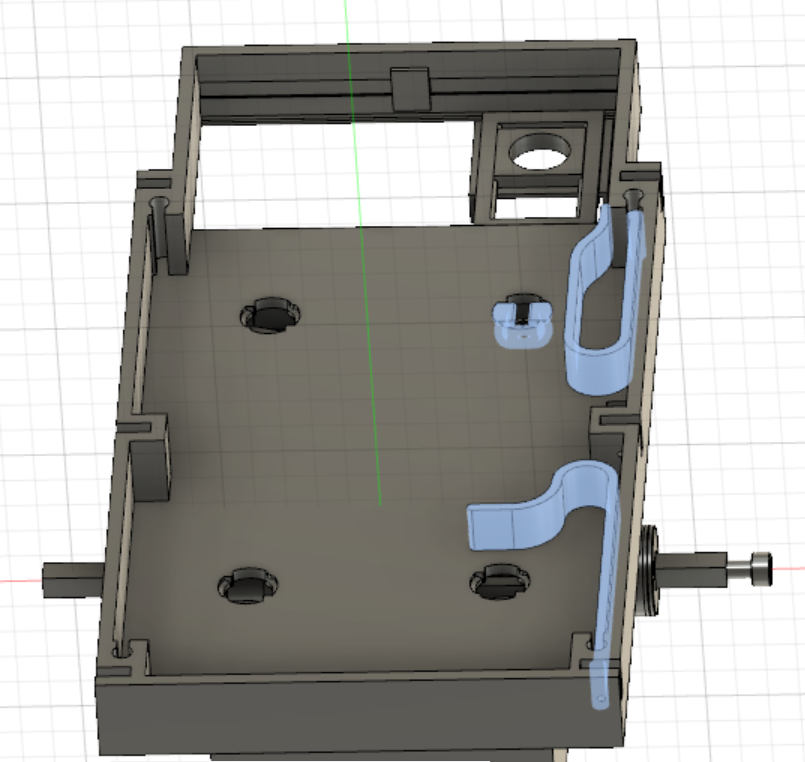
The phone holder is designed for an iphone 4, to use it for a different model phone will require a redesign of the phone holders, which are highlighted in blue on the side. These are necessary if you want to use a phone to get video from Sojourner and they should be duplicated for the opposite side as well. The blue part in the hole connects the phone holder to the main chasis, this part needs to bend when being inserted so it recommended that a flexible material be used here. Four of these should be printed, one for each hole. They are inserted turned 90 degrees from where they are in the picture and then turned back to the correct position.
Solar Tray
Figure 6: The solar tray
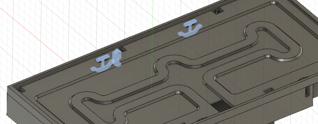
The solar tray is connected on top of the phone holder by these parts highlighted in blue. Make sure to use a very flexible material for the anchor shaped parts because they need to bend to fit in and parts that small can very easily snap. The middle part fits in on the outside of the phone holder and should be secured with an alignment pin. Extra parts should be printed for the other side of the solar tray and in case any parts break during assembly.
Main Chassis
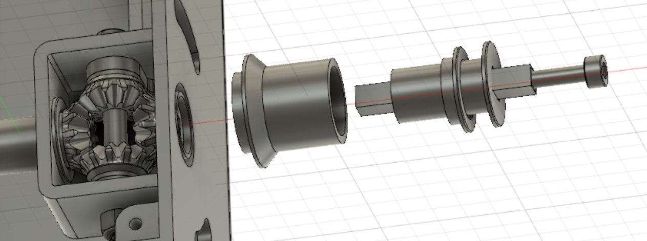
The rocker bogie connects to the main chasis as shown, with the screw going through the rocker bogie and into the main chasis, where a nut should be used to secure it in place at the end of the gear. This same process applies to the other side, just with a longer screw.
Figure 7: Rocker bogie chasis screw and gearbox
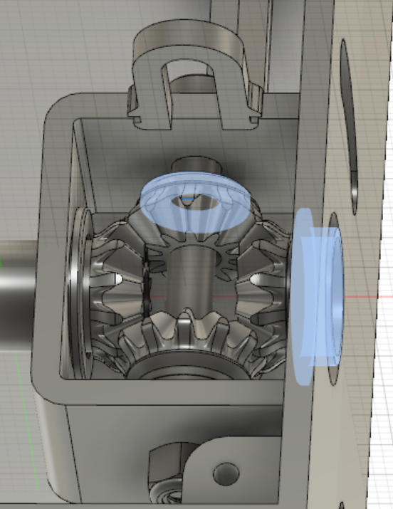
The gearbox can be tricky to fit in properly since the parts are so small. The two gears with square holes connect to the rocker bogie, while the two gears circular holes have a screw going through a cylindrical tube to hold them in place. Also note the washer next to the gear and the part labeled diff brush 240:1 that help keep the gears properly spaced. The horseshoe like should slot into the bottom of the gearbox and adds space between the gear and the edge of the box and also prevents it from being knocked out of place. In the bottom right corner, is where the phone holder is connected to the main chasis with a screw.
Figure 8: The gearbox
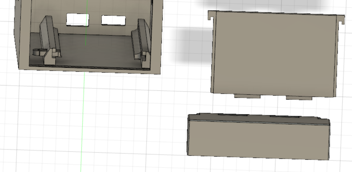
The last part of the main chassis the 3DoT holder, the two pcb rails should fit into the main chassis and connect to the holes on the bottom of the chasis with the pcb clip slotting into place to hold the pcb steady. The two holes at the back of the chasis should have enough space for you to turn on the 3DoT and plug in a micro usb to upload new code and charge it. When the 3DoT is in place the box and front cover can be slid into place.
Figure 9: The front panel and 3DoT holder
Mechanical BOM
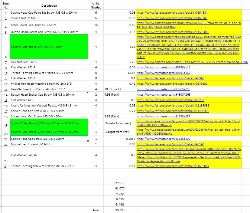
Before we go in depth with building, the cost and the amount of mechanical parts must be addressed. When purchasing parts such as the heat inserts for plastic, sources we used such as Fastenal and McMasterCarr did not have the parts available to buy individually. Reacting to this, while planning to the project in the beginning; we had to allocate more money to the mechanical parts as part of a contingency. Parts such as the Square Metal Tubing also brought their own problems later on the project. The square metal tubing had to be bought twice, as during the initial use, the tubing was cut too short, and since the tubing came in only about a foot of length; it needed to be reordered in order to create a tubing with the proper length.
Figure 10: Mechanical BOM
The Results
3D Printing
For 3D printing the parts we went to the innovation space here at CSULB, located in the library. They offer many different materials for printing and offer a student discount so they were the best option for our initial print. The discount they offer is per print with a minimum cost of $5 so we had all of parts printed in 2 orders instead of doing each part individually. Some of our parts needed to be reprinted due to errors in printing and general wear and tear over the course of the semester. For getting a couple parts reprinted we went to Maker’s Society because they were able to get the parts printed very quickly and we did not want to slow down on constructing the robot. The discount from the innovation space would also not apply as these smaller parts were below the minimum for the discount.
For our project we also received help from Jeff Gomes who generously helped us by redesigning and printing our servo mounts because our previous ones did not fit with the servos we had ordered.
Reflection
Some problems with assembling Sojourner can appear when ordering parts, we ordered are parts from Fastenal, although other stores also likely have the parts. Some parts might be out of stock and will require substitutions. In our case the servo was no longer in production and our new servo did not fit into the servo mount, requiring us to ask for help in redesigning and printing a new servo mount. Small parts can break or have errors when printing, it is recommended to order multiple copies of these parts in case anything happens to prevent delays.

