Solar Panel Testing and “Breadboarding”
By Zach Oyog (Electronics & Control)
Introduction:
The purpose of this post to test the voltage and current output of the solar cells. The information gathered from this study will determine if an additional protection circuit is required for recharging the RCR123A battery used in the 3DoT. According to 3DoT schematic, additional protection is required if the solar cell output exceeds a voltage of 16Vdc and current of 500mA. [1]
80×55 Solar Cell: [2]
- .6W Polycrystalline cell
- Working Voltage: 6V
- Transfer Efficiency: 17%
Test:
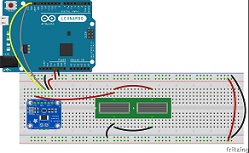
A simple circuit was designed using an INA219 high side current break out in the lead of the solar cells going into the V+ pin of the board with a common ground. The solar cells are two 80×55 cells placed in parallel. For use on the electronic breadboard, the micro-USB was removed but will be used in the final design to recharge the battery from the 3DoT. The cells were then tested in sunlight around 2 PM PST facing south-west towards the sun. Data was collected from the serial port in MATLAB to find the maximum current, minimum current, average current as well as the maximum voltage and average voltage.
/* Get Voltage for solar panel based on library from https://github.com/adafruit/Adafruit_INA219 * */ #include#include Adafruit_INA219 ina219; void setup(void) { Serial.begin(115200); while (!Serial) { // will pause Zero, Leonardo, etc until serial console opens delay(1); } uint32_t currentFrequency; ina219.begin(); ina219.setCalibration_16V_400mA(); } void loop(void) { float shuntvoltage = 0; float busvoltage = 0; float loadvoltage = 0; shuntvoltage = ina219.getShuntVoltage_mV(); busvoltage = ina219.getBusVoltage_V(); current_mA = ina219.getCurrent_mA(); loadvoltage = busvoltage + (shuntvoltage / 1000); Serial.print(loadvoltage); Serial.println(""); delay(300); }
/* Get current for solar panel based on https://github.com/adafruit/Adafruit_INA219
 *
 */
#include#include Adafruit_INA219 ina219; void setup(void) { Serial.begin(115200); while (!Serial) { // will pause Zero, Leonardo, etc until serial console opens delay(1); }
uint32_t currentFrequency;
// Initialize the INA219.
// you can call a setCalibration function to change this range (see comments).
ina219.begin();
ina219.setCalibration_16V_400mA();
}

void loop()
{
float current = 0 ;
current = ina219.getCurrent_mA();
Serial.print(current);
Serial.println();
delay(300);
}
% Sojourner Fall2017
% Zach Oyog
% using serial port data from arduino average the value of current form the
% ina219 high current sensor
% Note: MATLAB will display " Adruino *Model* detected" in the command window
%
close all
clear
clc

delete(instrfindall); % close exisiting ports
s = serial('COM5' );
s.BaudRate=115200 ; % match with Arduino Baud Rate

fopen(s) ; % open the serial port to record data
s.ReadAsyncMode = 'continuous' ;
readasync(s) ;
sample = ;

for i=1:sample
 serialdata = fscanf(s) ;
 flushinput(s) ;
 t = strsplit(serialdata, '\t') ;
 data(i,1) = str2double(t(1)) ;
end

delete(instrfindall); % close the serial port

%save("data") as voltdata or currentdata_solarpanel

%%
currentdata = struct2array(load('currentdata_solarpanel.mat'))
voltdata=struct2array(load('voltage_solarpanel.mat')) ;

avg_current = sum(data) / length(data) % mean() could save time...
max_current = max(data)
min_current = min(data)

avgc = ones(length(data))*avg_current ;
maxc = ones(length(data))*max_current ;
minc = ones(length(data))*min_current ;

sp = smooth(data, 0.3, 'loess') ;

figure(1)
hold on
plot( data, '.b', 'linewidth', 1.5); grid on ;
plot(sp, '.m', 'linewidth', 3 ) ;
title('Arduino Serial Port Data ')
plot(maxc,'.k' ,'linewidth', 3) ;
plot(minc,'.k', 'linewidth', 3) ;
plot(avgc,'.r', 'linewidth', 3) ;
title(' Current Measurements')
legend("Raw Data", "Smooth Data", "Max Current", "Min Current"," Avg Current");
hold off


avg_volt = sum(voltdata) / length(voltdata) % mean() could save time...
max_volt = max(voltdata)
min_volt = min(voltdata)

avgv = ones(length(voltdata))*avg_volt ;
maxv = ones(length(voltdata))*max_volt ;
minv = ones(length(voltdata))*min_volt ;

sp = smooth(voltdata, 0.3, 'loess') ;

figure(2)
hold on
plot( voltdata, '.b', 'linewidth', 1.5); grid on ;
plot(sp, '.m', 'linewidth', 3 ) ;
title('Arduino Serial Port Data ')
plot(maxv,'.k' ,'linewidth', 3) ;
plot(minv,'.k', 'linewidth', 3) ;
plot(avgv,'.r', 'linewidth', 3) ;
title(' Voltage Measurements')
legend("Raw Data", "Smooth Data", "Max Voltage", "Min Voltage"," Avg Voltage");
hold off
Results:
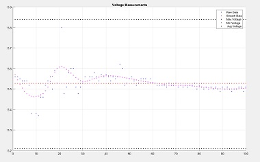
The recorded data showed that an additional protection circuit was not needed to recharge the battery from the solar cells. The average current was 41.735mA while the average voltage was about 5.5279 V. Although the averages were in the range if either voltage or current were to exceed the input of 3Dot, damage could be caused. However, the maximum current and voltage were well under the maximum input values, at maximum voltage = 5.84 V and maximum current = 42 mA.
Conclusion:
Without the need of an additional protection circuit, a step-down or regulator, the Sojourner rover is able to reduce mass and save space in the electronics box on the chassis. The solar panels will require manual “plug-in” to charge the rover while it operates or remains in direct sunlight.
[1] http://web.csulb.edu/~hill/ee400d/Technical%20Training%20Series/3DoT/Schematic_v5_03.png


