Sojourner Generation #3 Final Blog Post
Author/s: Cole Bailey (Project Manager) ; Sebastian De Arco (MST Engineer)
Verification: Cole Bailey
Approval: Cole Bailey
Table of Contents
Executive Summary
This project is focused on creating a scale model Micro-Sojourner toy. Our focus was to create a toy that could traverse multiple terrains, be intuitive to drive, and would be aesthetically pleasing. The Micro-Sojourner can be controlled like a traditional RC car through the ArxRobot app on your phone, or can be driven from afar using the Arxterra Control panel. This isn’t your classic Toyota or Honda Commuter, this is your weekend car and is meant to be showed off.
Program and Project Objectives
Program Objectives
The Robot Company (TRC) will be debuting its 2019 line-up of toy robots and associated games at the Toy-Invasion 2019 convention in Burbank CA on January 6, 2019. Your team’s assignment is to make the 3D printed and/or laser-cut prototypes to be showcased at the convention, prior to production starting in the second quarter of 2019. The robots will feature our new ArxRobot smart phone application and the Arxterra internet applications allowing children to interact and play games around the world. In addition, the robots should be able operate autonomously in game mode. See game(s) (i.e, mission objectives) assigned to your robot by the Game Division. To decrease electronics cost, interoperability between all TRC robots will be maintained by incorporation of the 3DoT board, developed by our Electronics R&D Section. Modification of downloadable content is limited to software switch setting and robot unique graphics of the smart phone and Arxterra applications. Modifications of electronics is limited to custom 3DoT shields as required by the unique project objectives of your robot. The Marketing Division has set our target demographic as children between the ages of 7 and 13, with a median (target) age of 11. To decrease production costs, please keep robots as small as possible, consistent with our other objectives. As with all our products, all safety, environmental, and other applicable standards shall be met. Remember, all children, including the disabled are our most important stakeholders. Our Manufacturing Division has also asked me to remind you that Manufacturability and Repairability best practices must be followed.
Project Objectives
This semester’s Sojourner team was focused on putting all the pieces together. We were given the hardware design, 3DoT micro-controller, and the Arxterra control panel/app. Our focus was on 3D printing and building the hardware, designing the custom firmware and electronics to drive all 6 motors and 4 servos, charging the 3DoT battery using a solar panel, and making the Sojourner as streamline and aesthetic as possible.
Mission Profile
Our Mission at the end of the semester is to traverse a miniature version of the Pathfinder path defined by Pathfinder generation 3. Through this course we are to demonstrate intuitive driveability, off-road capabilities, and charging through the Solar Panels.
Project Features
The features of the Micro-Sojourner include Solar Panels for charging, a PCB for extended control of the motors and servos, a 3DoT micro controller to interface with Arduino IDE, and a perfected chassis with a rocker bogie system from Jeff Gomes. To enable driveability from the Arxterra control panel we also included a smartphone tray with a periscope to relay the video feed from the phone on the Sojourner to the control panel on your computer. The rocker bogie system is designed for all terrains and will get your Sojourner where it needs to go.
Requirements
References:
- Arxterra / Classes / Engineering Method, select
 tab, scroll down to Requirements.
 - APPENDIX C: HOW TO WRITE A GOOD REQUIREMENT NASA Systems Engineering Handbook (page A:279)
- IEEE Guide for Developing System Requirements Specifications
Requirements and constraints are what drive the entire project. We are given customer expectations and constraints at the beginning of the project and must create a set of functional level 1 requirements that will meet those needs. From the level 1 requirements will come level 2 derived performance requirements. These derived requirements will include the system and subsystem specifications and should be created with you system block diagram in mind.
The constraints will come from the customer, external factors, or technical regulations. Constraints may include things like schedule, budget, or technical standards and codes.
Engineering Standards and Constraints
Project/Economic Constraints: (Cost, Extensibility, Interoperability, Maintainability, Quality, Marketability, and Schedule)
- Cost: All 3DoT robots should be constrained to a cost not to exceed $250. Sojourner will not exceed $400 because the cost of manufacturing and electronics needed.
- Schedule: All Project Schedules shall be constrained to a completion date of Monday May 13th, 2019. Project completion includes documentation and materials purchased by or loaned to the project.
- Economics: To demonstrate durability and child friendliness, the Sojourner should be dropped from a height of 1.4 meters, based on the height of an 11 year old girl.
- Extensibility: All 3DoT boards shall contain one or more custom designed 3DoT shields. The 3DoT shield incorporating interface electronics between the 3DoT board and sensors and/or actuators unique to the robot. (motors and servos for Sojourner) SMT will be employed.
- Maintainability: Disassembly and Reassembly of the robot shall be constrained to less than 20 minutes total. (10+10 min) (Sojourner shall implement connectors and wire bundling for quick assembly and disassembly)
Social and Ethical Constraints: (Accessibility, Aesthetics, and Usability)
- Accessibility and Marketability: The Sojourner should implement a speaker that creates an appropriate sound effect. This is to increase accessibility and marketability to the blind.
- Aesthetics: the Sojourner shall be designed in such a way that there are no dangling or exposed wires. This will include connectors and spaghetti tubing.
- Aesthetics: The Sojourner shall be designed by the form factor of the original, large scale, Mars Sojourner.
- Usability: The Sojourner shall be enhanced by adding an autonomous tank turn function and the use of the Arxterra phone and control panel application.
Manufacturability: (Constructability, Size, Weight, and Power (SWAP))
- Size: The size of the Sojourner electronics enclosure shall be constrained to be no greater than the 3DoT board, PCB shields, and associated mounting hardware.
- Power: The Sojourner shall use an external battery (Nitecore) that is located on the 3DoT board to provide power. All safety regulations as defined in section 4.3 Hazards of Failure Analysis of this document shall apply to the shipping, handling, storage, and disposal of LiPo batteries.
- Back of the envelope calculations and experiments shall be conducted to set the diameter of the power carrying wires. Follow the American Wire Gauge (AWG) standard when defining the diameter of power carrying wires.
Environmental Health and Safety (EH&S) standards: (Environmental standards, sustainability, toxic waste (Solar Panels), Health and safety, ergonomics)
- All standards, codes, and regulations as defined in the “Engineering Standards and constraints” section of this document shall apply.
- All Lithium batteries should be purchased with and stored, when not in use, in a fire and explosion proof battery bag.
Functional:
- All 3DoT robots shall incorporate the 3DoT v8 or later series of boards.
- Software shall be written in the Arduino De Facto Standard scripting language and/or use the GCC C++ programming language, which implements the ISO C++ standard (ISO/IEC 14882:1998) published in 1998, and the 2011 and 2014 revisions. Required exceptions to this standard can be found here.
- All 3DoT robots shall be in compliance with the 3DoT Command and Telemetry packet specifications.
- All 3DoT robots shall be controlled via bluetooth 4.0 in compliance with the Bluetooth Special Interest Group (SIG) Standard (supersedes IEEE 802.15.1)
Level 1 Requirements
Functional Requirements
- The Sojourner shall traverse a predefined course based on the Pathfinder generation 3 course.
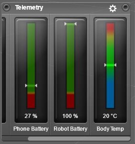
- The Arxterra Control Panel shall display the custom widgets and custom telemetry for the 3DoT battery level, phone battery level, and orientation of the bot.
- The Sojourner shall charge itself through USB using a 3 cell solar panel during missions at a current between 100 and 300 mA depending on the amount of sun exposure.
- The cable routing of the sojourner should be clean and efficient to reduce the chance of wires getting caught on terrain and to increase aesthetics.
- The Sojourner should turn using a slip differential around a radius of 1 meter.
- The Sojourner shall be driveable using the D-Pad and custom controls on the Arxterra Control panel and App.
- The Sojourner will use a smartphone camera to stream a video feed via Arxterra Control Panel.
- The Sojourner shall be a downscaled toy model of the original JPL Sojourner.
Level 2 Requirements
References:
- Arxterra / Classes / Engineering Method, select
 tab, scroll down to Defining Level 2 Requirements.
 - APPENDIX C: HOW TO WRITE A GOOD REQUIREMENT NASA Systems Engineering Handbook (page A:279)
- IEEE Guide for Developing System Requirements Specifications
System/Subsystem/Specifications
2.1.1 The Sojourner shall traverse the predefined course in less than 5 minutes
2.1.2 The Sojourner course shall be 15 meters long.
2.1.3 The Sojourner course shall include a 180 degree turn demonstration
2.1.4 The Sojourner course shall include ascending an incline.
2.1.5 The Sojourner course shall include descending steps 27mm high.
2.1.6 The Sojourner shall finish the course on one full battery life.
2.2.1 The Control Panel 3DoT battery level shall display when the battery level drops below 20% and needs to be charged.
2.2.2 The Control Panel Phone battery level shall display within 5% accuracy at all times while connected.
2.2.3 The Control Panel shall display the general direction and tilt of the sojourner using the smartphone gyroscope.
2.3.1 The Solar Panels shall produce between 5 and 7 Volts and 100 to 400 milliAmps in full sun to charge the battery.
2.3.2 The Sojourner battery shall take no longer than 2 hours to charge half way while in direct sunlight and being unused.
2.4.1 The wires coming from the Motors shall be mounted along the rockers using notches and clips to prevent them from dangling.
2.5.1 The Sojourner shall implement magnetic motor encoders for each motor to give RPM feedback.
2.5.2 The magnetic motor encoders shall provide feedback within 5 RPM of the actual value (within 5% error).
2.5.3 A custom control code shall use the encoder feedback to ratio the wheel speed on both sides of the Sojourner to create the differential turning.
2.5.4 The wheel speed ratio shall be directly proportional to the angle of the servos while turning.
2.6.1 The Sojourner shall go forwards and backwards using the front and back arrow keys on the D-Pad.
2.6.2 The Sojourner shall use differential turning by using the left and right arrow keys on the D-Pad while moving forward.
2.8.1 In order to replicate a down-scaled version of the real Sojourner, our Sojourner shall use micro-metal gear motors to fit the wheel size.
2.8.2 The micro-metal gear motors shall provide enough torque to drive the Sojourner comfortably. The Mass of the Sojourner is .5 Kg and our 6 motors combined have enough torque to drive a load of 1.418 Kg (3 times the weight of the Sojourner).
2.8.3 In order to replicate a down-scaled version of the real Sojourner, out Sojourner shall use sub-micro servos to turn the 2 front and 2 back wheels.
2.8.4 The sub-micro servos shall provide enough torque to turn the servos under the weight of the Sojourner. The maximum load of of the servos are .218 Kg, which is well above r ⅙ the weight of the sojourner (.083 Kg).
Allocated Requirements / System Resource Reports
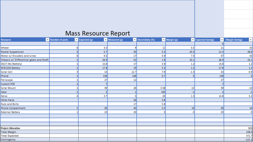
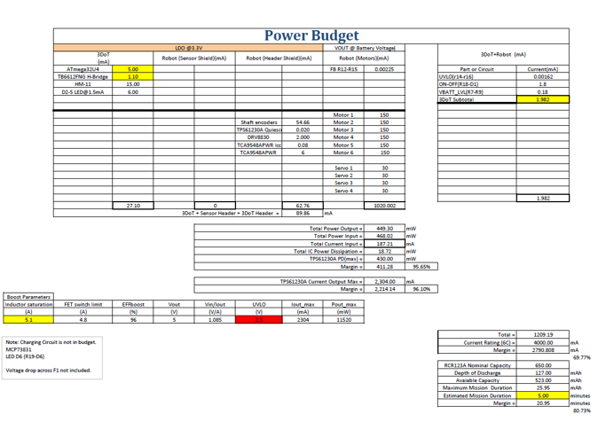
Allocated requirements, also known as resource reports, are written and tracked by the System Engineer. The types of resource reports are based on the project. For example, power allocation/estimate for each subsystem module of a spacecraft would be important, while a more loose tracking for a toaster would be in order. Each resource should have a margin attached to it based on the uncertainty in the estimate. It should also show contingency, where contingency is defined as the project allocation minus the estimate plus total margin.
Project Report
Project WBS and PBS
Project Work Breakdown Structure (WBS)
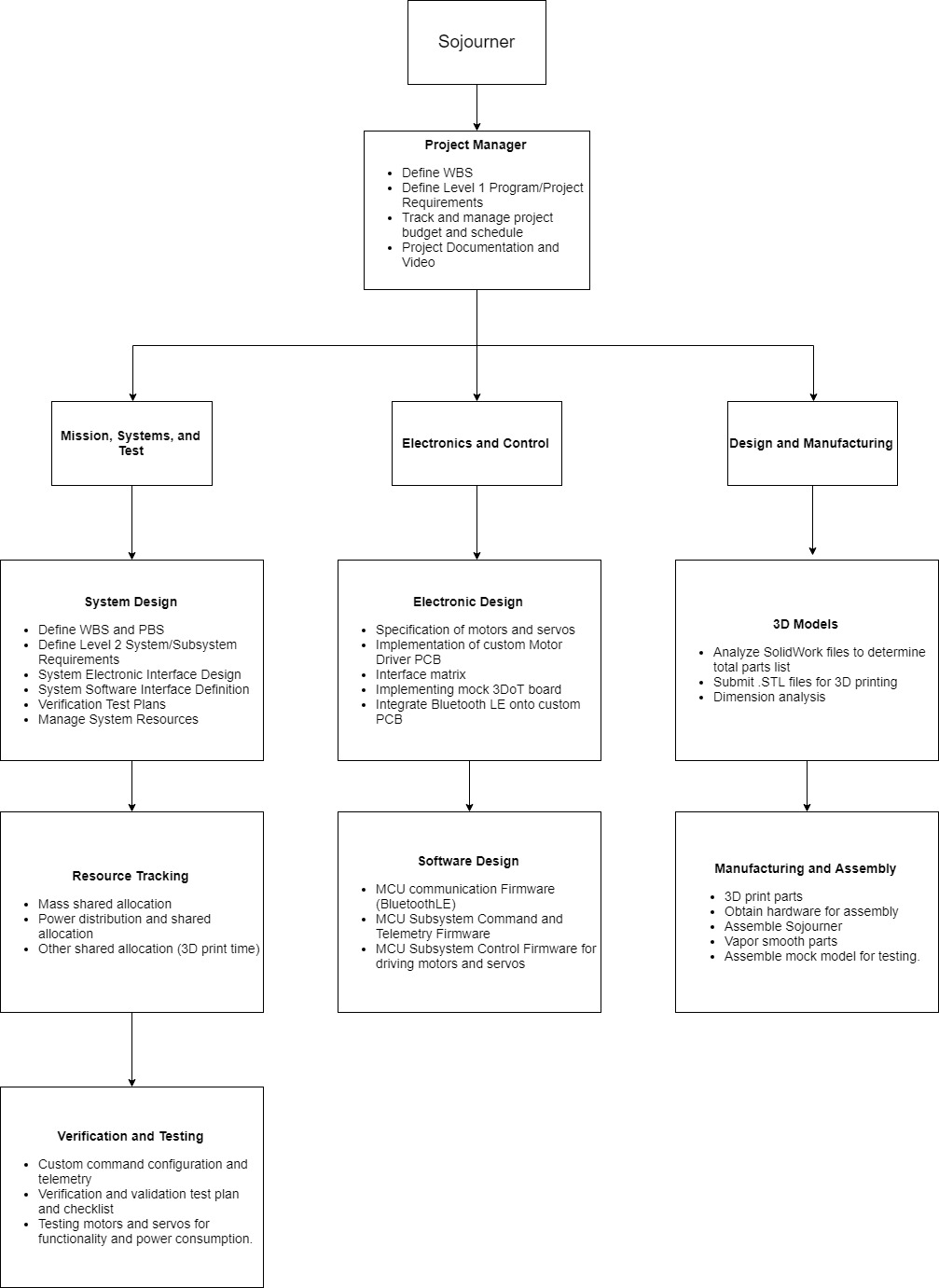
The Work Breakdown Structure (WBS) is an overview of the work, split up into appropriate sections (PM, MST, D&M, E&C), that needs to be accomplished for the project. It starts with the Project Manager tasks which includes defining the WBS, defining Level 1 Requirements, tracking/managing project budget and schedule,, and further project documentation and video. From there it is split up into the separate divisions of Mission, Systems, and Test, Electronics and Control, and Design and Manufacturing.
MST division tasks include System Design, Resource Tracking, and Verification and Testing. System Design tasks are defining WBS and PBS, defining Level 2 Requirements, electronics interface design, and software interface definition. Resource Tracking is finding the mass shared allocation, the power allocation, and other shared allocations such as 3D print time. The last part is Verification and Testing which involves testing custom command configuration and telemetry, testing motors and servos for functionality, and developing the Verification Test Plan and checklist.
Electronics and Control tasks are split into Electronic Design and Software Design. For the Electronic Design the tasks include specifying motors and servos, design of custom Motor Driver PCB, defining interface matrix, and implementing mock 3DoT board. For the Software Design the tasks were writing control firmware for driving motors and servos, as well as the telemetry firmware.
Design and Manufacturing tasks are divided into 3D Models and Manufacturing and Assembly. The 3D Models tasks are analyzing the SolidWork files to determine total parts, dimension analysis, and submit .stl files for 3D printing. The Manufacturing and Assembly tasks are to 3D print the parts, obtain hardware for assembly and assemble, and assist in mock model for testing.
Product Breakdown Structure (PBS)
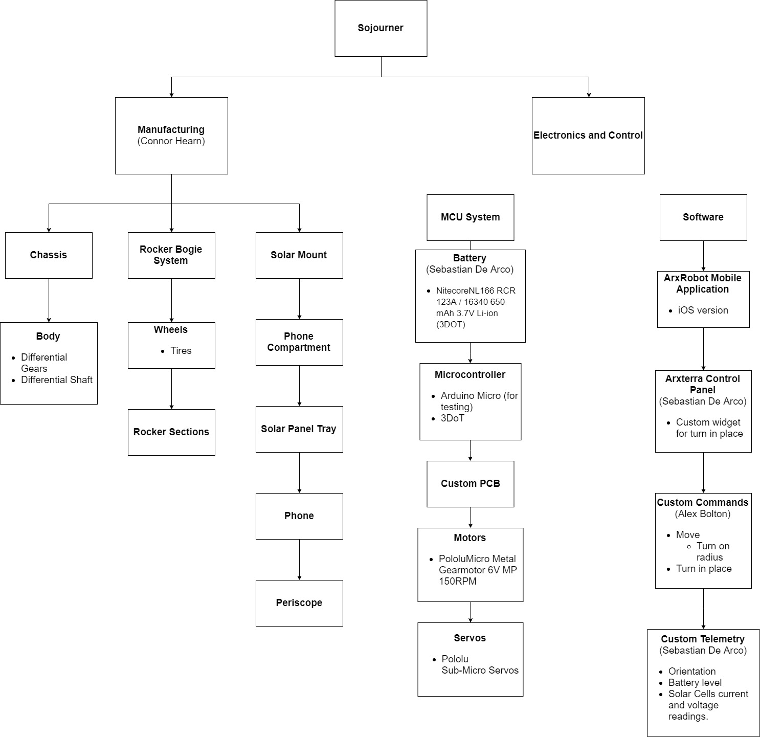
The Product Breakdown Structure is a breakdown of the products such as hardware items, software items, and information items. The PBS lives in the WBS and differs in that it outlines the products to be built or bought instead of the work to be done. The lowest level of the PBS should contain products for which a specific engineer is responsible. The PBS for the Sojourner is divided into sections for Electronics and Control and Manufacturing and Assembly, as in the WBS.
Elecronics and Control is further split into MCU System and Software. MCU System consisted of the battery, microcontroller, Custom PCB, Motors, and Servos. The Software section included Arxrobot Mobile App, Arxterra Control Panel, custom commands, and custom telemetry. The custom commands will be a modified move command and a custom turn command. Telemetry involves orientation, battery level, and solar cells current and voltage readings.
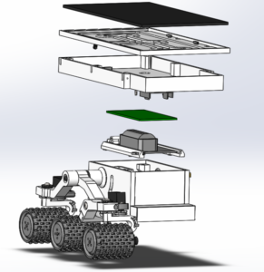
Manufacturing and Assembly splits the project into three mechanical subsystems: chassis, rocker bogie system, and solar mount. The chassis is the body with the differential gears and differential shaft inside. The rocker bogie system includes the wheels, tires, and the rocker sections. The solar mount includes the phone compartment, solar panel tray, phone, and periscope
References:
- Chapter 4, section 3 of the NASA Systems Engineering Handbook titled “Logical Decomposition” includes a section that briefly covers the Product Breakdown Structure (PBS.) Chapter 6, section 1 titled “Technical Planning” includes a section that explains the relationship between the Work Breakdown Structure (WBS) and the PBS. The PBS is the responsibility of the systems engineer. There is not quite enough information between these two sections to create a long presentation; instead focus on first going over the info, and then work with your division members to create an example PBS during the meeting.
- NASA SE Handbook Sections 4.2, 4.3-2, 6.1-4/5,G-1
- Arxterra / Classes / Engineering Method, select
 tab, scroll down to The Robot Company Work Breakdown Schedule.
 - WBS and PBS PowerPoint by Avi Sharma
Cost
The list below details all of the items purchased for the Sojourner. The only items not listed are the Arduino Micros that each team member used to test, reprinted gears, and the PCB parts and board. This was not included because we funded it ourselves. There is no Margin or Contingency because any extra parts will be funded by the Sojourner team.
| # | Vendors | # of Items | Items | Cost
$ |
| 1 | Amazon | 1 | OSOYOO Bluetooth 4.0 HM-10 Master Slave Module | 9.99 |
| 2 | Amazon | 2 | Adafruit Dual H-Bridge motor Driver | 12.68 |
| 3 | Amazon | 1 | Ugreen Micro USB cable | 4.79 |
| 4 | Pololu | 6 | Micro Metal Gear motors | 103.67 |
| 5 | Pololu | 2 | Magnetic encoder pair kit | 17.90 |
| 6 | Pololu | 4 | Servos | 19.80 |
| 7 | Texas Instruments | 5 | 1A Low Voltage Brushed DC Motor Driver with Speed Regulation (I2C Ctrl) | 22.72 |
| 8 | Ebay | 5 | ANBES Solar Panels | 22.45 |
| 9 | Battery Junction | 1 | Nitecore battery NL166 – RCR 123A | 10.44 |
| 10 | Makers Society (CSULB) | 2 | Sojourner 3D printed chassis and parts. (Reprint included in this price) 60+20 | 80.00 |
| 11 | Amazon | 1 | HiLetgo PCA9685 16 Channel 12-Bit PWM Servo Motor Driver IIC Module For Arduino Robot | 6.99 |
| 12 | Amazon | 1 | Periscope | 5.99 |
| 13 | Amazon | 1 | Striveday 26 AWG Wire | 16.39 |
| Total | Total | Total | ||
| 13
Purchases |
32
Items |
$333.81 |
Schedule
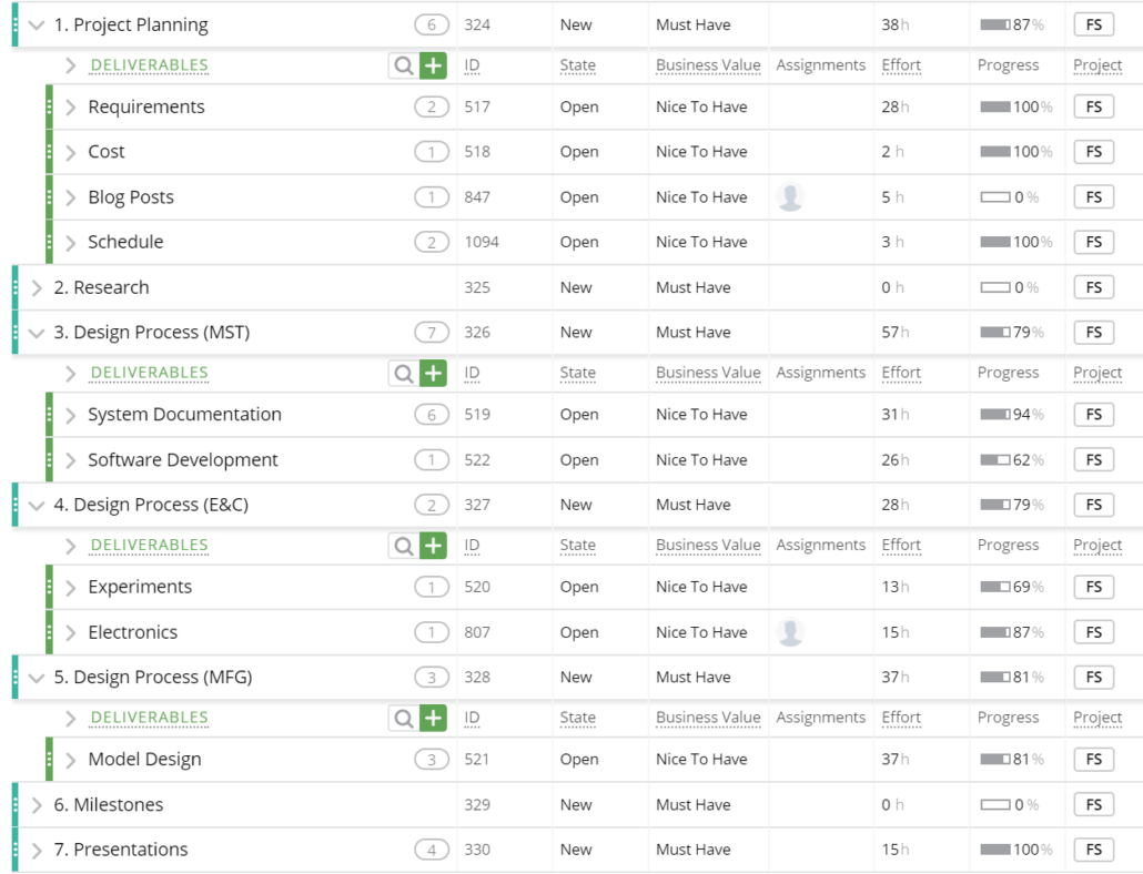
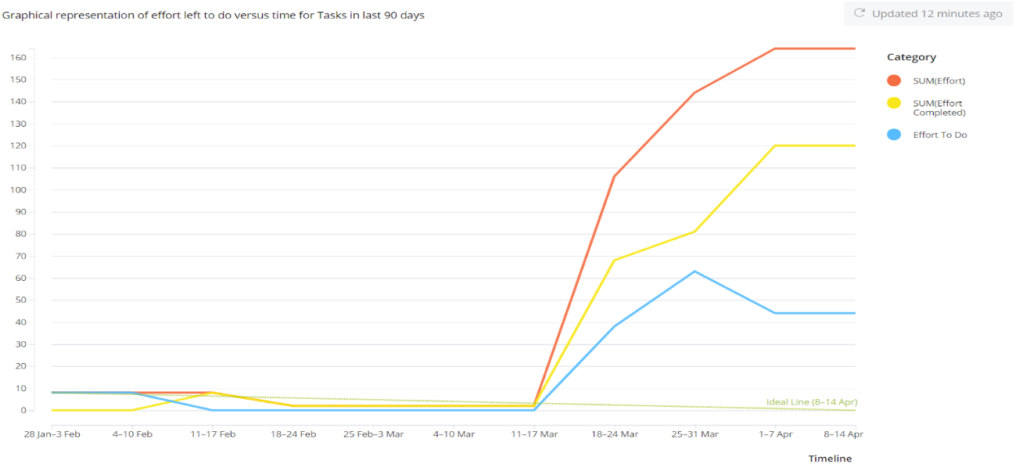
Burndown and/or Percent Complete
Concept and Preliminary Design
The total mechanical design for the Sojourner had already been completed by Jeff Gomes and was provided to us. There were only minor design modifications to account for the specific electronic components used.
Design Innovation
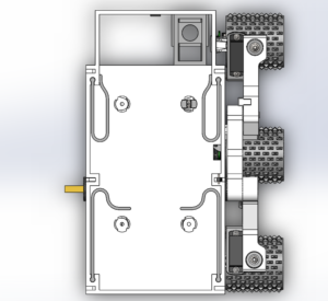
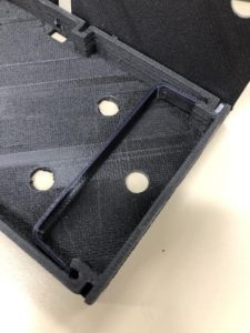
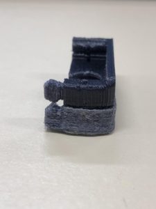
The phone springs on the left were in the original design and were meant to fit an iPhone 4s, but we only had an iPhone 7. So the phone spring was changed to the design on the right to compensate for the larger size of the iPhone 7.
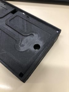
The barrier to keep the solar panel wires in position was sanded down at the bottom of the solar panel tray. This is because a hole was made to go through the solar panel and phone tray so the wires from the solar panels and usb can be in closer proximity to the micro usb port which is located at the back of the sojourner. Using the original design would have resulted in having the micro usb cable wrap around the side to back of the Sojourner. The solar panel wires can go through the bottom of the solar panel tray, into the open space below the phone spring in the phone tray. The solar panel wires are then connected to the micro usb cable in that area. The micro usb cable is fed through the hole in the phone tray and to the micro usb port.
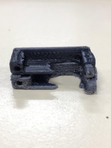
Theses are pictures of the servo mounts. The original prints and designs are on the bottom and the redesigned and new prints are on the top. The original servo mounts did not fit the servos that we got, so an extruded cut had to be made on the back on the mounts, as seen from the left picture. Additionally, the fittings that held the mounts in place did not come out well when printed because there was a lip at the end of the mounts that ended up merging with the fittings, making the bottom of the fitting one flat surface. So the lip was cut off and the servo mounts were reprinted.
System Design / Final Design and Results
The major subsystems of the Sojourner design are the 3DoT board, one custom PCB for additional motor drivers, one custom PCB for servo drivers, Solar Cells for charging, and phone for communication from 3DoT to control panel.
The 3DoT board is the microcontroller used to control the Sojourner via Bluetooth communication with a phone/control panel and the Arxrobot library. The 3DoT will drive two motors and servos, communicate with the Arxrobot app via bluetooth, charge the onboard battery via USB, and provide the interface for the PCB’s to accomplish additional requirements. Finally the code written based on the Arxrobot library will be uploaded to enable control of Sojourner via our custom commands.
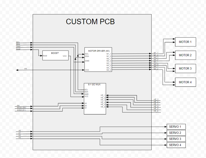
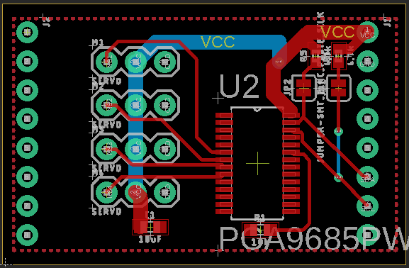
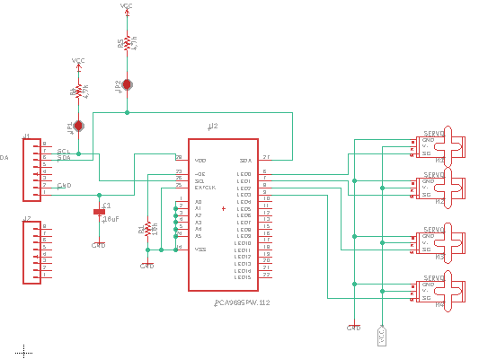
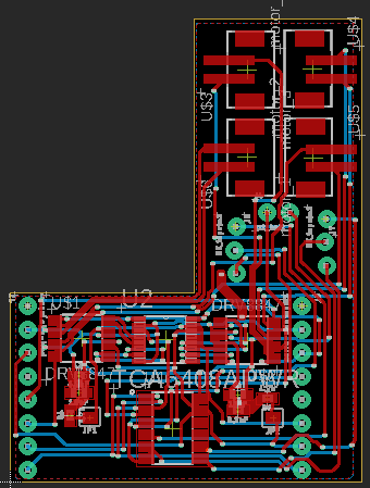
The first custom PCB will be mounted on the 3DoT to enable the Sojourner to run four more motors and two more servos. It will contain four I2C communication based motor drivers, connections for an external battery to power the motors, a buck converter for the external battery, and a multiplexer for the shaft encoder telemetry. The second PCB will have an additional I2C communication servo driver to enable the use of four servos.
The solar panel mounted on the top of the Sojourner will have three solar cells in parallel to enable charging of the on-board battery via USB connection.
The phone compartment will store the cell phone used for control of the Sojourner through the Arxrobot App. The phone will communicate with the 3DoT through Bluetooth LE, and then the phone will connect to the Arxrobot Control Panel to provide a video feed, telemetry, and to control the bot.
System Block Diagram
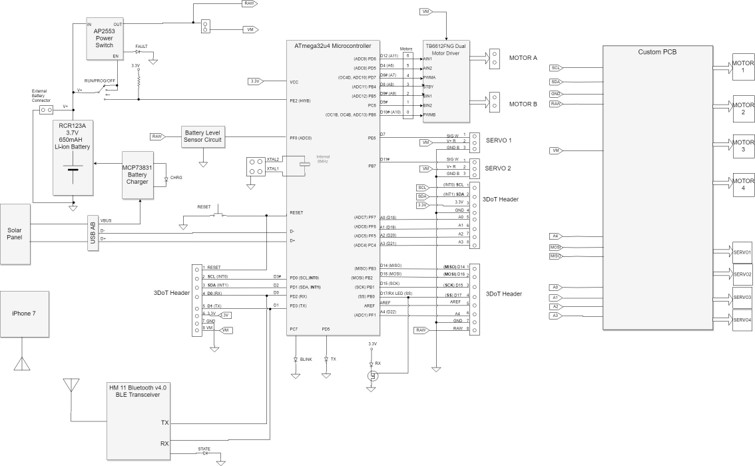
The system block diagram above shows the detailed connections of the 3DoT along with the added subsystems. The 3Dot contains one sensor header with analog inputs, two other headers for the other connections, two servo headers, two motor connections, and one external battery connection. Two motors and two servos will be connected directly to the 3DoT. It also contains the HM-11 Bluetooth communication chip and a battery charging circuitry.
The additional subsystems that will be added are the solar panel with 3 cells, two custom PCB’s, and a phone for control. The custom PCB for the motor drivers will be mounted on the two headers in an L shape configuration to avoid clipping with the battery and will contain JST connections for the motors and the external battery. This is modeled as the block on the right of the diagram. This is shown in the following seperate block diagram:
The other custom PCB for the servos will be mounted on the servo header pins located on the 3DoT and also contain connectors for the servos. The phone compartment and solar panel tray are one component. The phone will be put in the compartment and the solar cells will be put on the top tray designed for them. The wiring for the solar cells will run underneath in set grooves and go through holes in the phone compartment/solar tray, and then out the back to the USB connection. The solar panel is shown on the left hand side of the diagram connected to the USB port, which leads to the battery charging circuitry.
Interface Definition
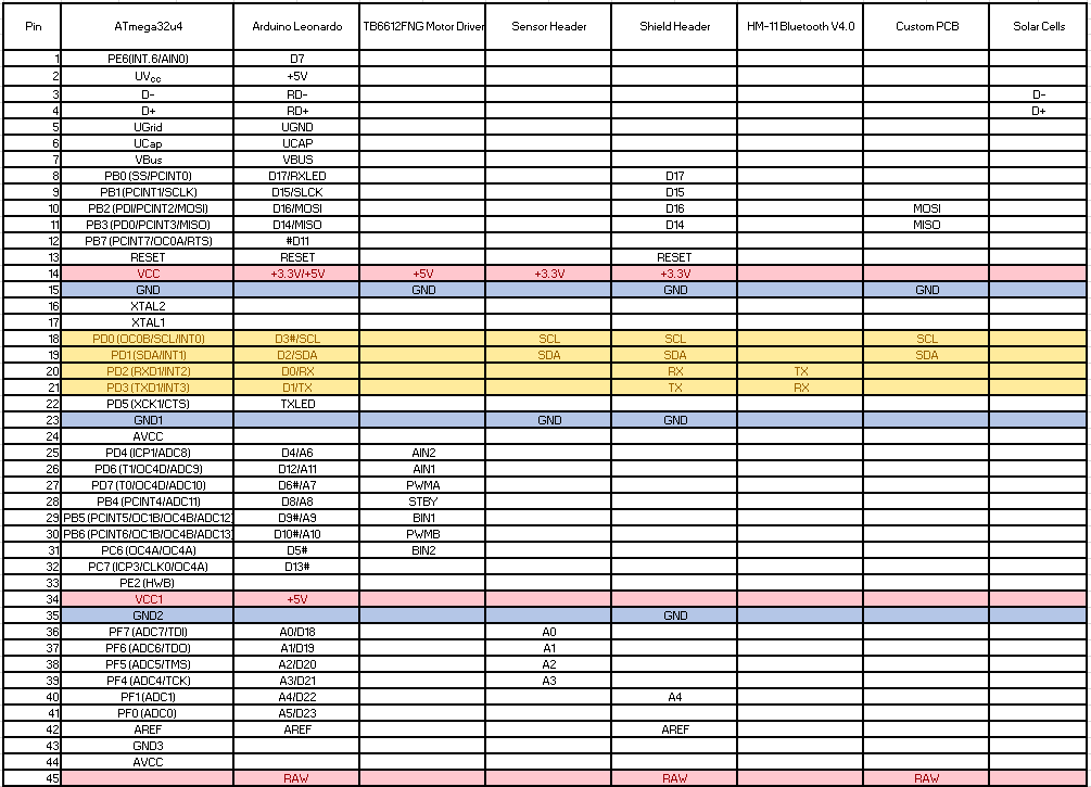
This is the Sojourner 3DoT Interface Matrix which shows the connections between the 3DoT and the other subsystems.
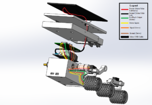
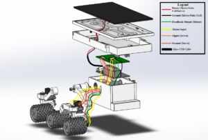
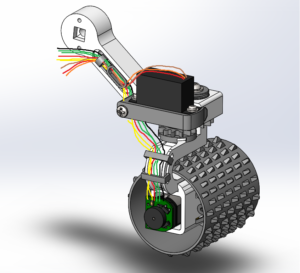
Cable Tree is the wiring diagram showing how the components will be physically connected on the Sojourner. The following were created using the SolidWorks design files.
This cable tree picture is a back end view with loose wiring to show where they will be routed into to the chassis and connected on the 3DoT or PCB.
This is a front end view with loose wiring to show connections and routing.
This is a more accurate view of how the wiring from the motors will be routed along the inside of the rocker bogie sections.
Modeling/Experimental Results
References:
- Arxterra / Classes / Engineering Method, select
 tab, scroll down to Design Process and Modeling.
 - IEEE Guide for Developing System Requirements Specifications
The following table describes the major designs, revisions, and things learned for the Sojourner. These contain the general idea, but to find information on the specifics, see our individual blog posts.
| Blog Posts | Model | Description/Example |
| Motors | Full scale model | Includes experiments and Calculations. We used the specs from Pololu and their torque curves to verify that our motors had enough torque to drive the Sojourners weight with plenty of room for error. We also experimented with the motors and used different loads (by pinching the rotor) and found the max and min current draw from each motor. See the blog post for the details. |
| Servos | Experiments | Tested servos on the sojourner chassis with the expected load. We kind of had to wing this one by ordering the servos before hand and testing them, but we found that the servos have plenty of power to angle the wheels. |
| Encoders | Experiments | We drove motors directly from a power supply at a constant speed and recorded the revolutions per minute. We verified its accuracy by counting the revolutions(easily counted by watching, it’s only 150 RPM max). The code is provided in the Blog Post. |
| PCB | Calculations and trade off studies | We went through many versions of the PCB before we got to print it. Our PCB is coming in two stackable pieces to save space and simplify the wire cabling. We decided on all of the parts of the PCB by necessity for the system to work. The motor drivers and servo drivers needed to be changed to I2C communication, we needed to add a GPIO expander for the motor driver inputs, and we added connectors for the motor drivers, servos, and external battery. All of the details are described in the Blog Post. |
| Battery supply (external) | Experiment and calculations | We were originally going to use the NiteCore battery to power all of our motors and servos, but we expected that it would not supply enough instantaneous current for the initial surge and would cut out. We now have a 2s 7.4V LiPo battery (Tattu) being used through the Vm pin on the 3DoT to drive all the motors and servos.Our initial calculations for the power budget showed that we did not need the external battery with such a high current output, but we did not take into account the surge when you first start the motors. |
| Solar Panels | Experiments | We used multiple loads and various degrees of sun to test how the solar panels would perform. Once we had somewhat reliable data showing they would not fry our 3DoT, we plugged it into the Arduino Micro and checked the current/voltage. Once we found that it was charging correctly we then tried it on the 3DoT and measured its current and voltage. More about our results in our blog post. |
| Chassis | Full scale model | Our chassis was already designed by Jeff Gomes, but it was difficult to put together. We had to do multiple reprints of different parts, a ton of sanding, cutting, and jerry-rigging to get it to go together. We created a couple design solutions that included wiring the solar panel through the phone tray and re-designing the phone tray clip for an Iphone 7. For more information, check out the blog post. |
Mission Command and Control
3DoT Robots
This section provides a systems level look at the software modules employed by 3DoT robots. This section represents a collaborative effort by the system and electronics/control engineers.
| Hardware | Software |
| Personal Computer | Arxterra Control Panel |
| Smartphone | ArxRobot App |
| 3DoT Board | Arduino and Robot3DoT Library |
As shown above the hardware that will be used is a personal computer, an iPhone smartphone, and the 3DoT v8 board. The software that will be implemented is the Arxrobot Arduino Library written in C++, the Arxrobot app connected on the phone, and the Arxterra control panel connected to the phone on the bot.
The code that will be utilized for Sojourner is the Arxrobot Move command handler, the telemetry gauges on the control panel, and servo command handlers using the Arduino Servo library. Control of the additional four motors and the servos will also be done using I2C communication, which will utilize the Arduino Wire library.
The Arxrobot Move command handler will be modified to allow the operation of the four additional motors using the Arxterra Control Panel directional pad. The servo control will be done using custom servo commands to control two servos simultaneously or individually. The custom widget used to control the servos will be radio buttons with predefined angles and sliders to individually control servos.
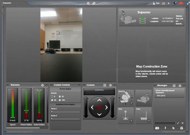
Telemetry gauges to be shown on the Arxterra Control Panel, such as the motor speed (measured using magnetic shaft encoders) and MCU internal temperature, were enabled in the Arxrobot mobile app. The custom command widgets for controlling the servos (radio buttons and sliders) were also created and programmed in the Arxrobot app. The following is a screenshot of the Control Panel with our features:
Other Telemetry gauges
Electronic Design
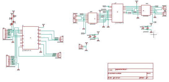
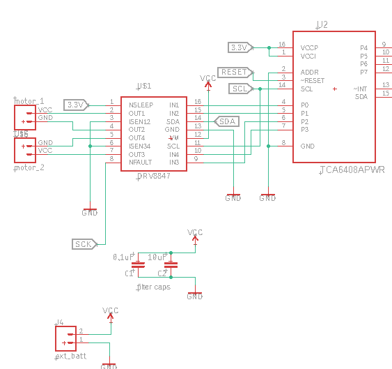
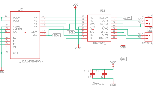
This semester, the PCB was designed to control 4 servos and 4 motors with the ability to read 6 Hall Effect Sensor. We used 2 DRV8847 motor drivers, which was a dual H-bridge, allowing us to drive 2 motors per driver. Since the DRV8847 required 2 inputs per each driver, we implemented the TCA6408 GPIO expander which gave us 8 extra IO pins to give signals to our drivers. To connect to our motors, we are using non-reversible JST connectors. The PCB allows for an external battery, which will be used to power each of the motor drivers as well. To reach each Hall Effect Sensor, we added an 8:1 Multiplexor (TCA9584) to reach each one. We allocated 3 pins to our MUX to select an input, which will be cycled through in our code. To drive our servos, we added a stackable board for our main PCB which contains a PCA9685 Servo driver. This allowed us to connect 4 servos from one IC. All of our parts use I2C communication systems which allows us to use one pin from the 3DoT Board to send and receive data to our ICs.
PCB Design
Firmware
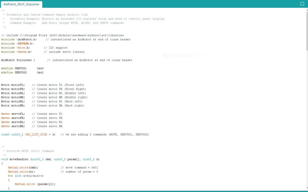
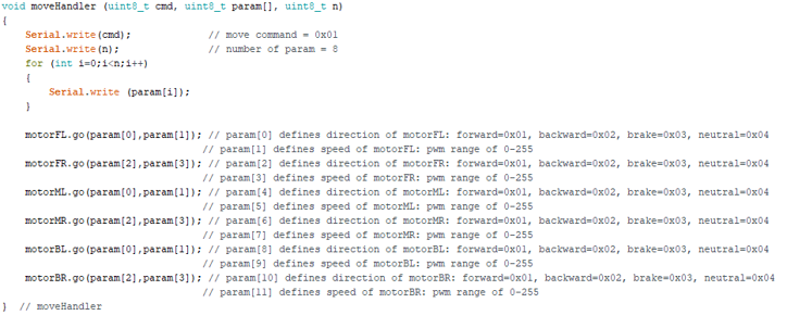
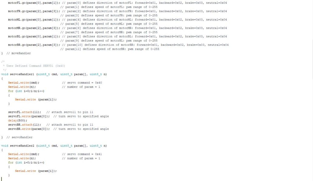
The firmware for the Sojourner is based off the Arxrobot TelecomClass example program provided in the Arxrobot Library.
First the six motors and four servos need to be instantiated and the Arduino Wire library needs to be included for I2C communication control. The command list size also needs to be modified to include the new custom commands (MOVE and SERVOS).
Next is the custom MOVE command to override the default MOVE. This will include control for the additional motors.
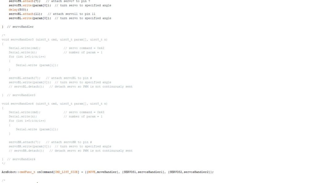
The custom commands to control two servos at once is implemented to achieve turning capabilities for the Sojourner.
Mechanical/Hardware Design
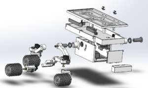
Here is an extruded model of the sojourner design that Jeff Gomes made.
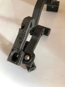
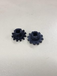
Here are pictures of our initial parts compared to our current parts. The picture on the left shows part of the bogie system that was printed in Carbon Fiber ABS, on the left, and the current parts were made in Polycarbonate ABS which provided smoother parts. The right picture shows our servo gears printed in Nylon. On the right of the picture, there is the original print of our servo gear that had supports between the gear teeth that needed to be cut off. The left shows a reprinted version that did not have the supports and the teeth were a lot cleaner.
Verification & Validation Test Plan
Reading and Resources:
- Arxterra / Getting Started / Systems Engineering / Missions, Systems and Test Timeline
- Week #7 – Product Verification & Firmware Setup
- Week #8 – Product Validation & Cable Tree/Cable Routing Diagram
- Sample Verification and Validation Plans
Test Plan:
| Requirement # | Shall Statement | Verification success criteria | Verification method |
| 1.1,
2.1.1, 2.1.2, 2.1.3, 2.1.4, 2.1.5, 2.1.6 |
Course Description | 1. Sojourner will completely ascend the incline. 2. Sojourner will completely descend three stairs. 3. Sojourner will make a full 180 degree turn within 1 meter. 4. Sojourner will complete the entire course (15 meters) in one battery life. 5. Sojourner shall finish the course in under 5 minutes. | Demonstration |
| 1.2,
2.2.1, 2.2.2, 2.2.3 |
Control Panel Telemetry | 1. The Control Panel will display the correct phone battery level within 5% at all times. 2. The Control panel avatar will display the correct orientation and direction . 3. The Control Panel shall display custom widgets to control the servos. 4. The Sojourner battery level will decrease on the display when the battery reaches 20%. | Test |
| 1.3, 2.3.1, 2.3.2 | Solar Charging | 1. The Solar panel will increase the battery level while charging in the sun (no movement). 2. The Solar Panel will charge the battery from 3 to 3.7 Volts in 3 hours while stationary. 3. The Solar Panels will charge the battery with a current less than 600 mA. 4. The Solar Panel will charge the battery with a voltage between 5 and 7 volts. | Test |
| 1.4, 2.4.1 | Cable Routing | 1. There will be no loose hanging wires on the Sojourner. 2. Each motor and servo set of wires will be bundled for neatness. 3. Each bundle of wires will be secured with a mount. 4. Connections will be made with connectors and not solder. 5. The wires will be clipped on the side of the rocker bogie system. | Inspection |
| 1.5, 2.5.1, 2.5.2, 2.5.3, 2.5.4 | Differential Turning | 1. The Sojourner shall receive RPM feedback within 5% error 2. The wheels on each rocker section (left compared to right) shall move at different speeds while turning. 3. The ratio of speed of opposing motors shall be proportional to the angle of the servos. | |
| 1.6, 2.6.1, 2.6.2 | Control Panel Drive Controls | 1. The Control panel will move the Sojourner forwards and backwards using the D-Pad. 2. Control panel will implement a tank turn. 3. The Control Panel will turn the servos left and right. | Demonstration |
| 1.7 | Arxterra Video Feed | 1. The control panel will display the phones video feed. 2. The video feed shall be clear through the periscope. 3. The Periscope shall be adjustable to create the best field of view. | Inspection |
| 1.8, 2.8.1, 2.8.2, 2.8.3, 2.8.4 | Downscaled model Sojourner | 1. Our sojourner shall look like a downscaled version of the original JPL Sojourner. 2. The Motors shall provide enough torque to drive the Sojourner. 3. The Servos shall provide enough torque to turn the wheels. | inspection , Test |
| Cost, Schedule, mass, 3DoT | Major Constraints | 1. Sojourner will implement a 3DoT board.2. Sojourner will be 3D printed. 3. Total weight of the Sojourner will be less than half a kg. 4.Sojourner will cost less than $400. 5. Sojourner will be done by May 13th. | Inspection |
Concluding Thoughts and Future Work
This section includes your thoughts on how the next generation product could be improved, lessons learned the hard way or how would you do things different if you could go back in time.
What You Should Know:
- Communicate often and listen to the customer.
- If you think something will take an 2 hours, plan to double it so you get it done right.
- Know why you are buying parts, before you buy them.
- Don’t procrastinate.
At this point, the Sojourner should be operating somewhat properly. We should be able drive and turn reliably from the Control Panel. All 6 motors should be powered from the external battery through the PCB, all 4 servos should be able to turn from the 3DoT and PCB connectors, and the control panel is set up in a way that is intuitive to control.
What to do next:
Make it better. Plain and simple. This was a quick version of what this robot could be. Now that we have a “skeleton” of a bot driving around, its time to take it to the next level. Things to be done are:
- Improved wire cabling for assembly and disassembly
- Integration of the encoders for live stream feedback
- Reprint parts with optimal materials
- Improved internal design for space efficiency
- Integrate sensors to serve a purpose (heat detection, autonomous driving, water detection,etc.)
- …or even make it waterproof?
References/Resources
These are the starting resource files for the next generation of robots. All documentation shall be uploaded, linked to, and archived in to the Arxterra Google Drive. The “Resource” section includes links to the following material.
- Project Video YouTube or Vimeo link (see samples linked to here)
- CDR (Google Slides)
- PDR (Google Slides)
- Verification and Validation Plan
- Solidworks Files(Zip)
- Fritzing Files (CDR)
- EagleCAD files
- Arduino and/or C++ Code (zip folder) Linked to in Software Design Blog Post
- Complete Bill of Materials (BOM) mechanical
- Complete Budget

