Sojourner/Spring/2019
Custom PCB Layout
Author/s: Alexander Bolton
Table of Contents
Introduction
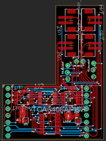
The 3DoT Sojourner Robot needs to drive 6 motors, run 4 servos, and read data from the shaft encoders. This semester, two stackable PCBs were created to preform the desired functions listed above.
Design (Main PCB)
The design for this custom PCB was initially loosely based on the previous semester’s design. However, due to changes in power allocation and functionality of the PCB, the design has reverted to a state more like the Fall 2017 Sojourner’s design. This portion of the design handles only with the control of the motors. It includes 2 dual motor H-bridges (DRV8847), a GPIO Expander (TCA6408APWR), and an 8:1 Multiplexor (TCA9548APWR). Due to the limited number of analog pins on the top shield of the 3DoT board, I2C Communication Protocols were used to send and receive data from every IC used in the design. The previous design had used the DRV 8830 motor drivers, which utilized I2C addresses by setting pins A0 and A1 to high, low, or open.
Initially, the PCB was designed to run off the battery power supplied from the 3DoT board. Unfortunately, since the battery only supplied a max of about 3.7 V, a complicated boost circuit would have been necessary for our design. To circumvent the issue of implementing a boost, an external power source (2S 45C LiPo battery) was chosen instead. The new issue with the battery was the variance of the voltages; it could vary from 6.4V to 8.4V. The DRV 8830 motor drivers utilized a small range of voltages, around 3 to 6 V, which the driver could accept as inputs. Because of this, the DRV 8847 were implemented, rather than the DRV 8830. The advantage of using the new drivers is its wide range of voltage inputs, from 2.8V to 18 V. This is desirable for our new design, because it takes a lot of power to run all 6 motors and all 4 servos at once.
One of the disadvantages for using the DRV 8847 its need for analog inputs for each motor. While it’s compatible with I2C communication, it’s used for the PWM control of the motor, not the control for the direction. Because of this, the GPIO Expander was implemented. This allows us to control the motor driver inputs through I2C still.
While the control for each motor had been settled, there was still the issue of reading the hall-effect sensors for each motor. Since there wasn’t enough pins to read 6 motors, there was a need to find a way to read the information. An 8:1 multiplexor was picked as the best option to streamline all the data into a single pin. To further reduce the number of pins needed, the use of I2C was taken advantage of once again; this granted the 3DoT the ability to control each motor and read data from each encoder through two signal lines from the I2C lines.
Design (Servo Driver)
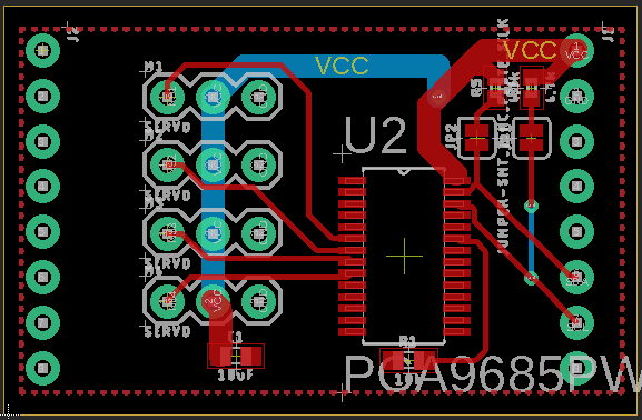
While the main PCB supported the operation of the motors, there was still a need to control each of the servos. To do this, the PCA9685PW was implemented to the design. The PCA9685PW offers the ability to send up to 16 PWM signals through I2C communication. This opens the opportunity to minimize signals going to the PCB to four signals, Vcc, Ground, SDA, and SCL.
This secondary board is intended to stack on top of the main PCB.
Troubles with the PCBs
After sending in the PCBs to be fabricated, receiving them, and testing them, it came to our realization that the power planes were not connected to the servo driver. While they were mislabeled to pins called VCC on the Eagle file, it was connected to the VM pin on the 3DoT board. One way to fix this issue is to change the VM label on the motor driver board to VCC, so it will connect to the VM pin on the 3DoT and the VCC plane on the servo board. This will allow both the servos and the motors powered through the 3DoT to be powered by the external battery as well.
Conclusion
The new custom PCB avoids possible power issues which could arise from using a lower voltage power source, by using an external battery and motor drivers with a wider range of voltage inputs. This comes at the trade off of more parts necessary for implementation into the Sojourner.


