Sojourner Spring 2020
Sojourner Sensorless RPM Firmware
Author: Alex Dalton
Verification: Robert Pearson
Approval: Chris Hirunthanakorn
Table of Contents
Intro
Editors Note: This code fills a traditional buffer using code that could be used to create a circular buffer.
Sensorless encoding is a method of gathering rpm data without the use of shaft encoders. One way to do this is through measuring the back emf generated by the motor between pwm signals. This can save weight, space, pins, and power as the sensors are no longer required. This post will be explaining the software we used to measure back emf through the 3DoT microcontrollers ADC.
Finite State Machine
For our testing code we use a finite state machine. The finite state machine let’s us add the code to our main code without stopping the processor on one part. The processor will only run the current state and then continue on to the rest of the code.
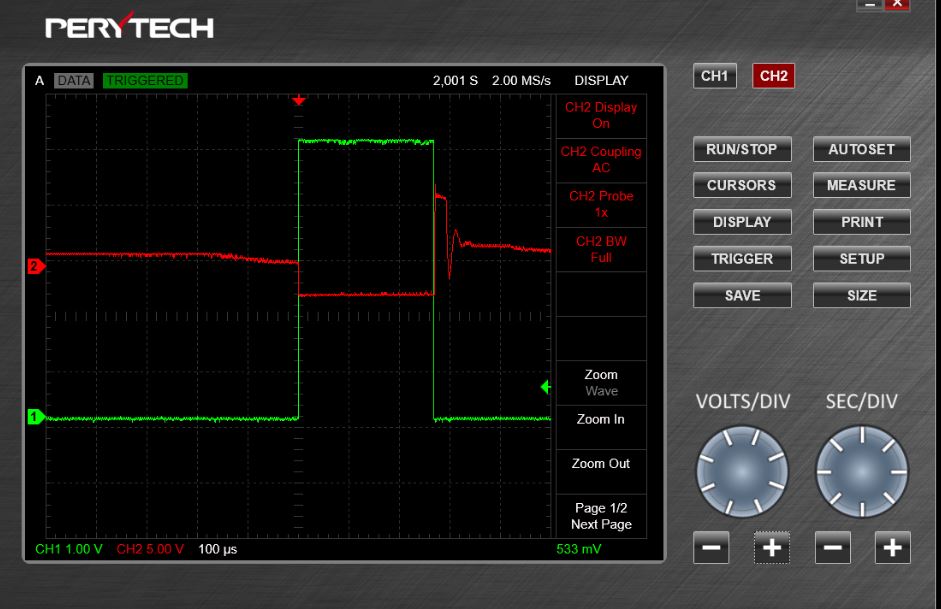
State 1 of our FSM starts with reruning until the PWM signal falls, it then moves on to state 1. In state 1 we have a delay before moving on to the next state. In the figure below the green line is the PWM signal, while the red is our back emf. The back emf spikes once the pwm drops, these values are not the ones we want and are too high for our ADC to handle at around 12V. As can be seen in the figure this high voltage eventually stabilizes which is the point where we want to get our readings and is why we included our delay. We then get our sample from the ADC and move onto state 2. In state 2 we print our result. With the running averager we add another state between 1 and 2 where we fill up a circular buffer and get an average value so that our rpm speed will be more stable.
Figure 1: Oscilloscope results from first back emf test
Code
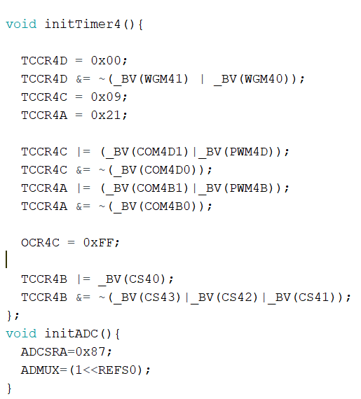
For our test we wanted the ADC to be able to grab values as fast as possible. Arduino’s libraries include the function analogread() for getting readings from the ADC, but this function re initializes the ADC every time it is run so we decided to create code to initialize the ADC only once and get readings faster since our the back emf method requires fast readings. This code shows how to initialize timer4 in fast pwm mode and also how to initialize the ADC.
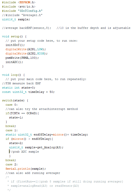
Our setup code for reading back emf values starts with running our code to intialize the 3DoT and the ADC. We also setup the motor and send a PWM signal to start it. We used a fairly low speed of 100 so we would have more time for our ADC to grab readings.
Case 0 of our finite state machine is an if statement to move to state 1 when the pwm signal switches from on to off. Another way to do this in a larger piece of code would be to use an interrupt attached to the drop of the pwm signal. The next part is creating a small delay so our motors will still run by using the micros() function. Micros() takes the current time on our timer and we use that value by adding the length of our desired delay to the current time. We then check if the timer has passed this value with our if statement and micros(). When the processor has passed this value we move into state 2 and grab a reading from our ADC. This was designed as an initial test so the running averager was not included and instead we use case 2 just to print the sample we took from the ADC. With the running averager we would grab enough values in case 2 to completely fill our circular buffer the first time the code is run or just add the new value we got from case 1 and drop the oldest one before taking the average and printing that result. After this the state goes back to the beginning
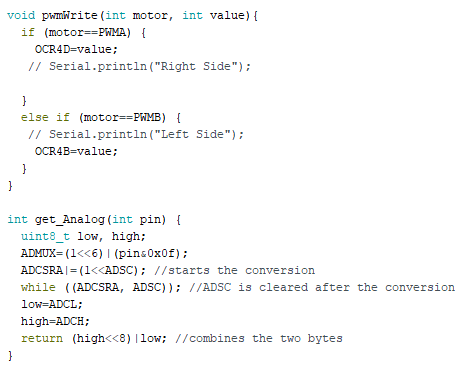
The last two functions of our code are pwmWrite and get_Analog. Pwmwrite sets our motor value and lets pick if we are going to be running motor A or motor B, although in this case we are only using motor A. The get_Analog function uses the ADC registers to start the conversion and get our back emf results.
What is an Averager?
A running averager or circular buffer is an averager based on recent values. As a new valueis received, the oldest value is removed. A running averager is performed over a certain number of data points and one of the design challenges is deciding what to do before the required number of data points has been received. One potential solution is taking a number of samples equal to the point value of the running averager when it is first run. The number of points that are used for the averager determines how much a single data point affects the results. Averaging over only 3 points means a new data point will have more of an affect on the final result than a 20 point averager, which can be an issue if you want remove noise from the data.
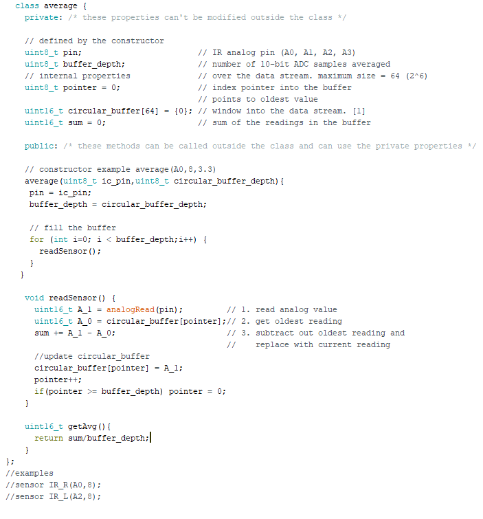
The code we wrote for our running averager uses a class based method. The average class is set up with two private properties: pin and buffer_depth, that are set when defined by the constructor. This allows us to use this method for multiple different pins and change the number of points we want to average over very easily. The three public methods we have are average, readSensor, and , getAvg. Average is our constructor which fills up our initial circular buffer values and defines the pin number and the depth of the buffer. The readSensor() method is a 3 step method that reads a new analog value, gets the oldest value, and adds the difference between our new value and old value to the sum of all values. We then replace the oldest value with the new one in our buffer and increment the pointer forward. The last method is getAvg() which is a simple one that divides the sum by the buffer_depth to determine the average value of our buffer.
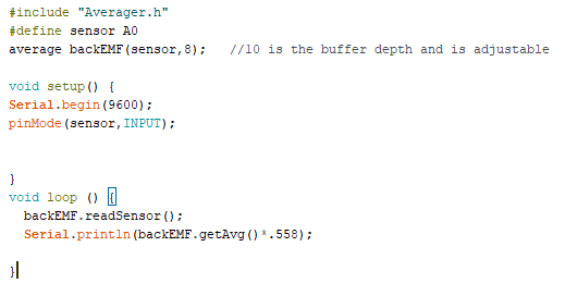
This is a short example of how these methods work in a main body of code. We include the averager class and define the pin we want to get readings from. The average method is used as our constructor outside of setup. For this example we are reading from A0 and are creating an 8 point moving averager. The loop for our code is just the readSensor method to get a new value and a serialprintln with getAvg() to display our moving averager result. We multiply the final result in this example since back emf results are proportional to the speed of the motors.
Design Parameters
To get the required data for our running averager we need to have access to the back emf generated by the motor. Since we only have access to one analog pin connected to the ADC and four motors that we want data from we need a way to switch between the motor we are getting results from. To do this we used a multiplexer(74HC4052D) that is controlled by the same PWM driver(PCA9685PW) used to control our motor drivers. We also needed to get our readings very quickly which is why we wrote our own alternative to analogRead().
Conclusions
In conclusion, we created code to quickly get ADC readings to protect our ADC and improve accuracy. We included a finite state machine so we could properly implement delay and separated our code into states so that it could later be added into our main code. We created a class based running averager to get an average speed over a number of points that we could adjust to get proper results.

