Spring 2017 Velociraptor: SolidWorks Hardware Design Model
Authors
By: Andrea Lamore (Manufacturing)
Approved By: Jesus Enriquez (Project Manager)
Table of Contents
Introduction
Throughout the engineering design process, the SolidWorks model for the Velociraptor went through a series of changes as our team went through trial and error with the different components for the robot. This post includes some of the thinking that went behind the hardware design of the robot.
Hardware Design
Servo Holder
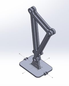
Previously we planned on 3D printing and ordering all the parts necessary to build out first prototype. I modified and added a few parts to the velociraptor skeleton in anticipation of some problems that might occur during the build phase.
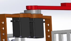
Mounts for the server were added to the bottom of the velociraptor for hip movement. Two or one servos could be placed here to accomplish hip rotation.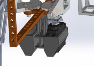
Head & Tail
Horizontal ball bearing will be used to facilitate rotation of the head and tail and the hip. The weight of the velociraptor is being supported by the legs, meaning that the body will resting on the hip mechanism which is attach to the legs – bearing will be added along the shaft of the hip that attaches to the leg. In order for the horizontal bearings to turn properly the outer and the inner radius of the bearing must not both be resting on the same surface. Circular extrusions for the parts resting on the bearing will be used to allow for proper slipping. The same horizontal bearing mechanism will be used to facilitate head and tail rotation.
Leg Mechanism
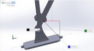
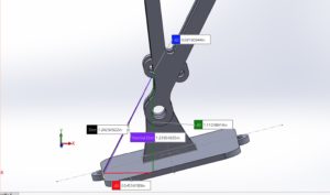
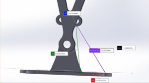
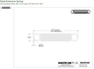
An issue with the Theo Jansen mechanism is the inability to keep the foot parallel to the floor is. Instead the foot moves in parallel with the legs circular motion. This means that that the whole body will shift back and forward with the foot motion when the velociraptor takes steps. With our first prototype, where we intended to use servos, a mechanical mechanism to keep the foot parallel to the floor could easily be incorporated into our design. A rounded out sole and a pair of springs attached to a pivoting joint at the angle was incorporated into the design in order to keep the foot parallel while it is carrying the weight of the velociraptor(when it is the supporting foot being used to stand). The rubber sole will give the velociraptor height in order to prevent the toe from hitting the floor on steps and to keep the foot from slipping.
Conclusion
After going through the design process, there was still consistent changes throughout the semester in terms of Hardware design as our team consistently went through prototyping. As a result, we ended up deciding to do most of the manufacturing through laser cutting instead of 3D printing according to our original plan.

