SPARCCS Spring 2016: Preliminary Design Document
By Mikhael Semaan (Project Manager), with contribution from
Jeremy Seiden (Systems and Subsystems),
Chelsea Mediavilla (Electronics and Control), and
Eric Hanna (Design and Manufacturing).
We review the preliminary design, including program and project objectives, requirements, system and subsystem design, work breakdown, and preliminary project schedule and plan.
Table of Contents
Source Material
- Hill, G. (November 2015). “The System Design Process.” EE 400D Documentation. Appendix A, 7-8.
- Hill, G. (Spring 2016). “The Preliminary Design Documentation.” EE 400D Documentation.
- SparkFun Electronics, Inc. (Accessed February 2016). “SparkFun Geiger Counter.”
- Linear Technology (Accessed February 2016). “LT8495 Low Q Current, 5V to 300V, 250kHz Flyback Converter.”
- Garcia-Moreno, E., E. Isern, M. Roca, R. Picos, J. Font, J. Cesari, and A. Pineda (April 2012). “Floating Gate CMOS Dosimeter with Frequency Output.” IEEE Transactions on Nuclear Science 59, 373-378.
- Wang, Y., N. G. Tarr, K. Shortt, I. Thomson (October 2003). “A sensitive floating gate MOSFET gamma ray dosimeter.” Sensors, 2003. Proceedings of IEEE 2, 1271-1276.
- Wikipedia (Accessed February 2016). “Dosimeter.”
- Vuono, N. (Fall 2015). “SPARCCS Fall 2015 Summary Blog.” EE 400D Blog Post.
- California State University, Long Beach (Spring 2016). “Final Exam Spring 2016 Schedule Charts.”
- Dunn, C., O. Rojas, R. Yancey, R. Leidenfrost, S. Cortez, M. William, M. Ho (Spring 2016). “Spring 2016 A-TeChToP Research Project.” EE 400D Blog Post.
- SparkFun Electronics, Inc. SparkFun Geiger Counter schematic diagram.
Introduction
This document forms the preliminary design of the Spring 2016 Space Radiation and Charging Cube Satellite (SPARCCS) EE 400D team (Team) project. We outline the Level 1 (Program / Project) and Level 2 (System / Subsystem) requirements, and show that they satisfy the criteria in [1]. We also introduce the block-level system design, interface definition, and a mock-up 3D model of our final product. Finally, we outline a rough set of task definitions for the project. This blog post as a whole pursues satisfying the requirements in [2].
Program Objectives / Mission Profile
(Mikhael Semaan, Project Manager)
NOTE: much of the following is either directly or indirectly taken from a Program Objectives statement given to the Team by the CSU Long Beach CubeSat Club (Club). We have not yet received explicit permission to link to this document, but the reader is advised to note the source of the following section.
The Spring 2016 SPARCCS Team shall develop a dosimeter to fit into the Club’s CubeSat Project chassis. The Team will do this in collaboration with the Club; the official liaison will be the Club’s internal Vice President. All funding will come from the Club and is capped at $250 USD for the Spring 2016 Team. The Team should have a representative present at every Club meeting to report on the Team’s progress.
The dosimeter will, for the time being, be based on SparkFun’s discrete, Geiger counter-based solution [3]. Initially, the Club suggested conducting a trade-off study with an IC-based solution [4]; however, focus has shifted to determining whether a solid-state-based solution is within budget [specifically 5 and 6, but in general also see 7]. Pursuing [4] would require a different Geiger tube, which eats roughly half of the operating budget, so for the time being studying it is not a priority. If the Team determines the Geiger counter to be the best solution for the dosimeter instrument, then the Geiger tube currently in inventory should be recycled to a new printed circuit board (PCB).
The dosimeter instrument should incorporate a microcontroller unit (MCU) which is able to receive a signal from the operating sensor (either Geiger tube or otherwise), put it through analog-to-digital (ADC) conversion if necessary, packetize the data in a format the Club is still determining, and output the packetized data through USB. Power supply will be provided; power is to be delivered through 5 V USB. Cabling, trace, and other shielding requirements remain identical to those of Fall 2015’s Team [8]. The board must consume no more than 500 mW of power.
Regarding the board size, preliminarily the same dimension as the board from Fall 2015’s Team is valid, except for the mounting hole locations. The Club wishes for the mounting holes to be centered on the corners. The whole package must not weigh more than 500 g.
Ultimately, the mission is to develop a dosimeter instrument board which is capable of measuring the total ionizing dose (TID) of radiation in the geosynchronous Earth orbit (GEO), fitting into the Club’s existing cube satellite infrastructure, and packetizing the sensor data in a Club-defined format.
Requirements
Self-Evaluation Rubric
(Mikhael Semaan, Project manager)
In light of our assignment [2], we do not define a method to verify our requirements. However, all other rubric criteria [1] are valid:
- Is the requirement Quantitative, Verifiable, and Realizable?
- Is the requirement located at the correct level?
- Is the requirement a response to a higher level requirement (or Customer Objective, in the case of Level 1)? Is the linkage clearly defined?
- Does the requirement provide links to source material?
- Does the requirement move the design process forward?
- Are equations used to calculate a provided requirement, and are the answers correct?
- The requirements that are missing are the hardest to discover and will be factored into the evaluation.
- Is the language in the form of a requirement?
- Avoid multiple requirements within a paragraph (i.e. break up statements which contain multiple requirements)
We adopt A-TeChToP’s [10] method of using a table to evaluate each requirement on a point-by-point basis; this is located in the “Self-Evaluation Rubric Table” Section. Here, we include some discussion.
Level 1 (Program / Project) Requirements
(Mikhael Semaan, Project Manager)
Program Requirements (PGR)
- The Spring 2016 Team’s project shall be managed by and operated in collaboration with the Club through its internal Vice President.
- SOURCE: Paragraph 1 of Program Objectives / Mission Requirements
- The Team shall report on the progress of their project during the Club’s general body meetings through at least one Team representative.
- SOURCE: Paragraph 1 of Program Objectives / Mission Requirements
- The cost of the project shall not exceed $250.00 USD.
- SOURCE: Paragraph 1 of Program Objectives / Mission Requirements
- All Requirements shall be met by Monday, May 09, 2016, the final exam date for EE 400D’s Wednesday section [9].
- SOURCE: See included reference. CSU Long Beach policy.
Project Requirements (PJR)
- The final product shall be integrated into a PCB of Club-defined size (tentatively 9.2 cm by 8.9 cm).
- SOURCE: Paragraphs 1 and 4 of Program Objectives / Mission Requirements. See [8] “Electronics Design” for size estimate.
- The final product shall implement a dosimeter capable of measuring the total ionizing dose (TID) of radiation in the GEO environment.
- SOURCE: Paragraph 4 of Program Objectives / Mission Requirements.
- The final product shall packetize the measured TID data into a Club-defined format (to be determined).
- SOURCE: Paragraph 4 of Program Objectives / Mission Requirements.
- The final product shall satisfy all power delivery and grounding requirements from Fall 2015’s Team project.
- SOURCE: Paragraph 3 of Program Objectives / Mission Requirements
- The final product shall consume no more than 500 mW of power.
- SOURCE: Paragraph 3 of Program Objectives / Mission Requirements
- The final product shall weigh no more than 500 g.
- SOURCE: Paragraph 4 of Program Objectives / Mission Requirements
Level 1 Requirement Evaluation
None of our Level 1 Requirements incorporate any calculations, so Point 6 in the Rubric does not apply. Even in the case of our board size, the requirement comes directly from last semester’s drawings. All of the requirements are quantifiable in some way; even PGR-01, -02, and PJR-02 and -03 (verification is not required in this document, but it may make the quantitative nature of these requirements clear, e.g. a written, formal document from the Club verifies our presence at their meetings). The source material, which also happens to be our connection to Objectives, is explicitly referenced in the Requirements. None of the Level 1 Requirements belong in a lower level, with the possible exception of PJR-01. It was chosen for Level 1 because Level 2 expands on the “size” constraint and goes into more detail, e.g. mounting hole placement etc. Each of the Requirements moves the design process forward: if any of these are missing, there are ambiguities that make it impossible to move the project forward. Finally, the language of all Requirements is suitable, and each “separate” Requirement is on its own.
Level 2 (System / Subsystem Requirements)
(Jeremy Seiden, Systems Engineer; with contribution from Chelsea Mediavilla, Electronics Engineer, and Eric Hanna, Manufacturing Engineer)
Electronics Subsystem Requirements (ELR)
- The Geiger counter (or other dosimeter device) shall be capable of measuring alpha, beta, and gamma radiation.
- SOURCE: PJR-02. While we have not shown that alpha, beta, and gamma are particularly prevalent in GEO, these are Club-defined (Mission Objective / Mission Profile) requirements which have not yet been fully fleshed out.
- The PCB shall utilize an Atmel 328P MCU (or a Club-approved equivalent) to parse packetized data from the sensor.
- SOURCE: PJR-03
- The PCB shall be capable of outputting packetized data through a USB interface.
- SOURCE: PJR-03, PJR-04
- The PCB shall receive power through a 5 V USB connection.
- SOURCE: PJR-03, PJR-04
Manufacturing Subsystem Requirements (MFR)
- All electronics on the PCB shall be mounted in place and grounded to the satellite chassis to prevent charge accumulation.
- SOURCE: PJR-04
- The complete board dimensions shall be 92 mm by 89 mm.
- SOURCE: PJR-01
- The PCB mounting hole size shall be 2.6 mm in diameter.
- SOURCE: PJR-01; referencing Fall 2015 Team’s board
- The mounting hole locations shall be 3.095 mm frmo the 89 mm side and 7.7 mm from the 92 mm side.
- SOURCE: PJR-01; referencing Fall 2015 Team’s board
Level 2 Requirement Evaluation
Electronics Subsystem
None of the Electronics Subsystem Requirements require calculations; thus, Point 6 of the Rubric does not currently apply. The requirements for measurement and data packetizing come directly from the Club and Level 1 Requirements are explicitly cited in the “Self-Evaluation Rubric Table.” These are suitable Level 2 Requirements due to the inclusion of specific functions of hardware/software. Each Requirement provides specifics for on-board hardware and thus moves the project forward. Finally, the language is appropriate and each Requirement has its own paragraph.
Manufacturing Subsystem
None of the Manufacturing Subsystem Requirements require calculations; thus, Point 6 of the Rubric does not currently apply. These Level 2 Requirements specifically pertain to the size and mounting specifications of the PCB as defined by the Club and the Level 1 Requirements. Dimensions are available through Fall 2015’s Team files. The requirements are quantifiable in that they contain specific dimensions and measurements. These requirements move the design process forward; without them, there would be no clear guideline towards actually manufacturing a working board. Finally, the language is appropriate and each Requirement has its own paragraph.
Self-Evaluation Rubric Table

Design Innovation
See the Spring 2016 Creativity presentation for details. We applied several creativity-fueling techniques to come up with both our requirements and potential design solutions.
System / Subsystem Design
(Jeremy Seiden, Systems Engineer; with contribution from Chelsea Mediavilla, Electronics Engineer, and Eric Hanna, Manufacturing Engineer)
Main System Block Diagram
(Jeremy Seiden)
The following is the high-level system block diagram.

Product Breakdown Structure
(Jeremy Seiden)
Below is a diagram which outlines our Product Breakdown Structure.

Electronic System Design
(Chelsea Mediavilla)
MCU: The MCU is fundamental to the board’s circuitry. The controller connects to the sensor, USB interface and power supply. Currently, the ATmega328 TQFP chip is being considered; however, a trade-off study will be done for the final selection.
Power Supply: Power is supplied to the printed circuit board by an outside source provided by the Club. We receive it as 5 V through USB.
Geiger Tube: The Geiger tube is the main sensor used for the board. The sensor (which may be replaced by a similar dosimeter) will measure alpha, beta, and gamma radiation pursuant to PJR-02 . The sensor is connected to the ATmega chip through the Universal Synchronous/Asynchronous Receiver/Transmitter (USART).
USB Interface: This interface is used to send sensor data to the satellite’s Command and Data Handling PCB as well as power the board.
System Block Diagram(s)

Interface Definitions
Interface Matrix
| ATmega32U4: Port Pin |
ATmega32U4: Function |
LND 712 Geiger Counter Pin | USB Pin | |
| 1 | PE6 (INT.6/AIN0) | Digital Pin/ Analog Comparator | ||
| 2 | UVcc | USB Pads Internal Regulator Input supply voltage | ||
| 3 | D- | USB full speed port; connected to USB D- connector pin | D- | |
| 4 | D+ | USB full speed port; connected to USB D+ connector pin | D+ | |
| 5 | UGnd | USB Pads Ground | ||
| 6 | UCap | USB Pads Internal Regulator Output supply voltage; connected to external capacitor | ||
| 7 | VBus | USB VBUS monitor input | VBus | |
| 8 | PB0 (SS/PCINT0)) | SPI Slave Select input/ Pin Change interrupt | ||
| 9 | PB1 (PCINT1/SCLK) | SPI Bus Serial Clock/ Pin Change interrupt | ||
| 10 | PB2 (PDI/PCINT2/MOSI) | Program Data Input/ Master Out Slave In/ Pin Change interrupt | ||
| 11 | PB3 (PDO/PCINT3/MISO) | Program Data Output/ Master In Slave Out/ Pin Change interrupt | ||
| 12 | PB7 (PCINT7/OC0A/OC1C/) | Output compare and PWM for Timer Counter0/ Output compare and PWM for Timer Counter1/ Pin Change Interrupt/ UART Request To Send | ||
| 13 | Reset | |||
| 14 | VCC | Digital Supply Voltage | ||
| 15 | GND | Ground | ||
| 16 | XTAL2 | Output from inverting Oscillator amplifier | ||
| 17 | XTAL1 | Input to the inverting Oscillator amplifier/ input to internal clock | ||
| 18 | PD0 (OC0B/SCL/) | External Interrupt/ Serial Clock/ Output Compare for Timer Counter0 | OUT | |
| 19 | PD1 (SDA/) | External Interrupt/ TWI Serial Data | ||
| 20 | PD2 (RXD1/) | External Interrupt/ USART Receive Pin | ||
| 21 | PD3 (TXD1/) | External Interrupt/ USART Transmit Pin | ||
| 22 | PD5 (XCK1/) | USART External Clock/ UART Clear To Send | ||
| 23 | GND | Ground | ||
| 24 | AVCC | ADC Supply Voltage | ||
| 25 | PD4 (ICP1/ADC8) | Timer Counter1 Input Capture Trigger/ ADC input | ||
| 26 | PD6 (T1//ADC9) | Timer Counter1 Clock Input/ Timer 4 Output Complementary Compare D/ ADC input | ||
| 27 | PD7 (T0/OC4D/ADC10) | Timer Counter0 Clock Input/ Timer 4 Output Compare D/ ADC input | ||
| 28 | PB4 (PCINT4/ADC11) | ADC Input/ Pin Change Interrupt | ||
| 29 | PB5 (PCINT5/ OC1A//ADC12) | Output compare PWM for Timer Counter1/ Pin Change Interrupt/Timer 4 Complementary Output Compare/ ADC input | ||
| 30 | PB6 (PCINT6/ OC1B/OC4B/ADC13) | Output compare and PWM for Timer Counter1/ Pin Change Interrupt/Timer 4 Output Compare/ ADC input | ||
| 31 | PC6 (OC3A/) | Output compare for Timer Counter3/ Output Compare and complementary PWMfor Timer 4 | ||
| 32 | PC7 (ICP3/CLK0/OC4A) | Input Capture Timer/ Divided System Clock/ Output Compare and direct PWM for Timer 4 | ||
| 33 | PE2 () | Hardware bootloader activation | ||
| 34 | VCC | Digital Supply Voltage | ||
| 35 | GND | Ground | ||
| 36 | PF7 (ADC7/TDI) | ADC input/ JTAG Test Data Input | ||
| 37 | PF6 (ADC6/TDO) | ADC input/ JTAG Test Data Output | ||
| 38 | PF5 (ASC5/TMS) | ADC input/ JTAG Test Mode Select | ||
| 39 | PF4 (ADC4/TCK) | ADC input/ JTAG Test Clock | ||
| 40 | PF1 (ADC1) | ADC input | ||
| 41 | PF0 (ADC0) | ADC input | ||
| 42 | AREF | ADC analog reference | ||
| 43 | GND | Ground | ||
| 44 | AVCC | ADC supply voltage |
The interface matrix was designed using the ATmega 32U4 chip pinout and the SparkFun Geiger Counter/USB schematic as references. The former is included below; the latter is found in [11].

Mechanical Design
(Eric Hanna)
The 3D rendering below illustrates a rough model of the final deliverable product: a board which incorporates the Geiger tube sensor and the other requisite electronics to interface with it. Physically, the main component is the Geiger tube, which needs to be flush with the outside of the satellite housing. However, this is preliminary, as our sensor choice is subject to change.

Design and Unique Task Descriptions
Manufacturing Engineer Tasks
(Eric Hanna)
- Lay out the PCB, working from the schematic provided by the Electronics Engineer
- Generate files to upload to PCB house for fabrication
- From Bill of Materials generated in EAGLE, create a shopping list of components for approval
- Purchase components for the PCB and SMT solder paste stencil
- Re-flow and hand-solder components as needed
- Give completed board to Electronics Engineer for testing
Electronics Engineer Tasks
(Chelsea Mediavilla)
- Perform trade-off studies for MCU, USB interfaces, and dosimeter alternatives
- Use Frizting Software and the Interface Matrix to diagram breadboard configurations
- Develop C++ software to test the Geiger Tube for radiation measurements
- Create Eagle CAD schematic for the Manufacturing Engineer
- Write software for the MCU to read the sensor using USART
- Write software to implement the USB interface using the MCU
- Test final PCB as delivered by the Manufacturing Engineer
Work Breakdown Structure (WBS)

Project Schedule
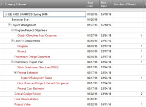
Top Level Schedule
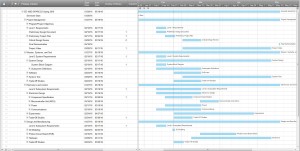
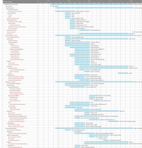
Below is the top-level schedule along with the top-level Gantt Chart.
 System-/Subsystem-Level Tasks

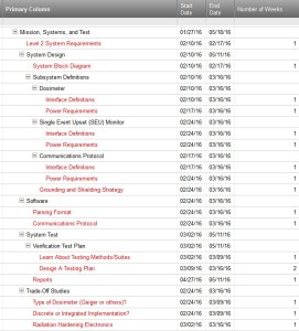
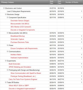
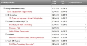
Building from the Top-Level Schedule, the specific system and subsystem tasks are in red.
Project-Level
 Mission, Systems, and Test

 Electronics and Control

 Design and Manufacturing

 All-Inclusive Gantt Chart

 Burn Down and Project Percent Completion

Since the Burn Down chart is a constant work-in-progress, we provide a link to the Google Sheet here.
System Resource Reports (Including Project Cost Estimate)
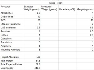
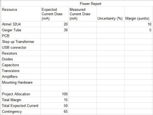
All of these reports can be found on Google Sheets here.
Mass Report
 Power Report

 Project Cost Estimate

