Spiderbot: Initial Design
By Simon Abatay, 3D Modeling and Manufacturing
Picking up from last semester’s Spiderbot project, the design for this project will have 6 legs. Though the name ‘spider’ implies 8 legs, translating it to a project would become very pricy in the long run since it would require more materials and power to construct.
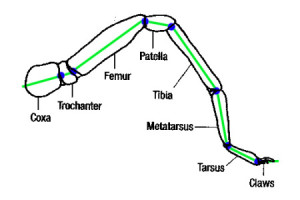
Despite the difference in leg amount, we still wanted the design to be similar to an actual spider. The image below is of an actual spider leg. From this, we can see that spiders have 7 joints.
(Image from: http://havoc20.wordpress.com/2010/11/13/spider-tibia-structure/)
This would translate to seven servo motors per leg, and at 6 legs that would mean 42 servo motors! To save money on the final design, we’ve reduced our spider leg design to the 3 main parts: the coxa, femur, and tibia. This is the case with most hexapod designs that can be found online.
Three joints with a single motion each will mean each leg will have three degrees of freedom. This reduction will provide smooth movement for Spiderbot while walking and enough support for the spider to stand when stationary.
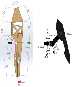
Keeping the reduction of joints in mind, the following image is my initial design of the spider’s tibia, which was created in the program SolidWorks.

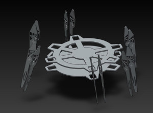
One of the main issues with last semester’s design was maintaining balance while stationary. To avoid this, each tibia portion will have a tibia “plate” on opposite sides of the servo motor. To keep the whole tibia portion from collapsing on itself, each pair of tibia plates will be supported by metal spacers or standoffs.
The tibia will measure 7 inches in height as a response to the project requirement of clearing an obstacle of 4 inches tall, located in the planned route for Spiderbot.
For the body portion of Spiderbot, I plan to use a circle-based design since its shape will alow for uniform weight distribution. This way, the tibias will be evenly spaced out and, assuming the hardware will be placed in the middle of it, the center of gravity will remain at the middle of the Spiderbot.

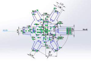
The image below shows the design of the base plate. The radius of the center portion is 3 inches to accommodate the power source, the microcontroller, the servo breakout boards, and the Android© based cellular phone.
The extensions of the circle have a radius of 4.4 inches to accommodate the servos and their proper positioning (see rectangular cutouts). The rest of the cutouts are for weight saving and heat ventilation. Seeing as a solid plate would have unwanted and unnecessary weight, it would be best to make cut-outs of the plate while at the same time leaving enough mass and surface area for the other components.


