Spiderbot Systems and Interactions
By Matthew Clegg – Computer & Control Systems
and Kristine Abatay – Project Manager
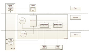
The following figure is a top-level systems diagram for the planned configuration of Spiderbot:
The method for powering Spiderbot from the Fall 2013 semester has been adapted at the moment, since the components used involved a NimH battery pack, as opposed to a LiPO battery, which would allow Spiderbot to meet the level 1 safety requirement.
This next figure was created by Matthew, using the program Fritzing, to show how the servos for Spiderbot will be connected to the microcontroller:
As was stated in a previous blog, Spiderbot will execute code using an Arduino Uno R3, which does not support the amount of servos that will be used. This will involve the use of breakout boards, which are shown in the diagram above. Power will be supplied to the Arduino Uno and the two breakout boards separately. In addition to providing accommodation for all of the servo motors, the breakout boards serve as a sort of “protection barrier” between the servos and Uno, which is an added bonus, considering it would be cheaper to replace a breakout board than it would be to replace an Arduino Uno.
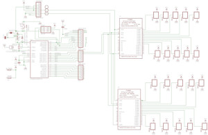
This final figure is a diagram, created by Matthew using the program Eagle CAD, displaying the connection of each individual operational component for Spiderbot:
These connections are described in the following interface matrix.
This diagram shows the allocation of pins of operational components of Spiderbot. Overlap between the components demonstrates interactions that will allow the servo motors to communicate with the microcontroller.


