Spring 2016 3D SMD: Conversion of EAGLE file to GCode: Initial Process
By Christine Vu (Missions, Systems, and Test) and Henry Nguyen (Electronics and Control)
Table of Contents
A preliminary simulation was conducted to determine how to convert a PCB design on EAGLE to a Gcode/CNC file for the Makeblock X-Y Plotter Robot Kit to operate. We set up an assembly line to provide an understanding on how the Makeblock X-Y Plotter Robot Kit has potential to pick up a component and place a component down. Future works depend on the development of the project. If time is available, software will be updated.
Fig. 1. Preliminary process of converting an EAGLE file to a GCode file.
Downloads:
- aceConverter: http://www.dakeng.com/ace.htm
- Notepad++: https://notepad-plus-plus.org/
Eagle Schematic & AutoCAD DXF File
We began the process of the EAGLE conversion with a PCB design. Screenshots of the process are shown below.
- Add 3 SMT capacitors size 0805 on the PCB (Or use any design)
- Go to File -> Switch to board
- Go to View -> Layer settings…
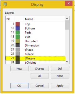
- Under Display -> Click None button -> Select Nr 23 tOrigins. This layer presents the origin of each component placed on the board
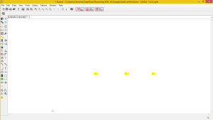
- Click Apply -> Click OK. The origins of the each component should only be show
- Go to File -> Export ->DXF
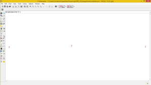
Fig. 2. A set of three 0805 capacitors placed on the EAGLE schematic.
Fig. 3. Display window of the EAGLE board. tOrigins was selected to show the origin of the capacitor (capacitor was placed on the top layer, t). Highlighted on the EAGLE board are the origins of each capacitor.
CNC File
aceConverter Download Link: http://www.dakeng.com/ace.htm
The Makeblock X-Y Plotter Robot Kit operates using Computer Numerical Control (CNC) files, which are often used with milling machines using G-code as the machine programming language. G-code are simply coordinates for a machine to navigate and trace. More information on understanding the G-code can be found here: http://www.tormach.com/machine_codes_gcodes.html
The DXF File exported by the EAGLE board was converted using a free open source application known as the aceConverter.
- Open aceConverter
- Click Open
- Select DXF File
- Click Convert
CNC File Macro
The control of the software was simplified with the implementation of a macro on Notepad++.
Information on how to run a basic macro is shown here: https://www.youtube.com/watch?v=Ks2u4MTTQbo
For our purposes, we set the macro to replace all Z-values with values to lift up (Z 18.0) and lift down (Z 34.0). After saving, this file, simulation was done to determine the placement of the reel feeders.
X-Y Plotter Simulation: NC Plot
An important aspect of the engineering method is the use of rapid prototyping and simulation. Before uploading GCode to the Makeblock X-Y Plotter Robot Kit to operate, a program was used to simulate the movement.
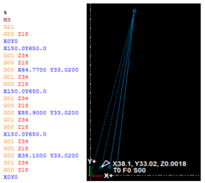
Fig. 4. Simulation of X-Y Plotter movement using NCPlot Program.
After using the macro in order to adjust all of our z-axis Gcode, we used a new software called NCPlot. This software is able to take .DXF and .Gcode files and simulate the actions of our X-Y plotter. I was also able to placed the reel feeder location X150.0 Y650.0 on the NCPlot editor directly. After finding the position of our reel feeder components, I was able adjust the Gcode to go to our reel feeders, pick up the component, head to the location of our first capacitor, and drop the component. This action was repeated for every component for our PCB. This program has great simulation features that allows us to visually see what our Gcode is doing. After verifying the simulation, we were able to send this file directly to our GRemote GUI and have our machine perform as expected.


