Spring 2016 3D SMD: Me Uno Shield and Software
By Henry Nguyen (Electronics and Control)
Table of Contents
Introduction
Originally when purchasing our X-Y plotter from MakeBlock, we were given a Me Orion microcontroller. This microcontroller was enough to power two stepper motors for our X and Y movement; however, because we are modifying our X-Y plotter to become a 3D SMD pick and place machine, we are required more stepper motors for our Z-axis and A-axis (rotation). Our solution was to purchase a Me Uno Shield ($10.00) from MakeBlock which has the capability to control four 12v stepper motors.
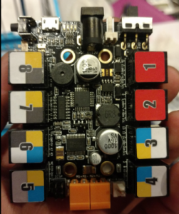
Me Orion
Figure 1. Me Orion Front
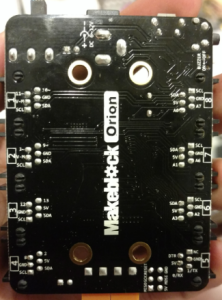
Figure 2. Me Orion Back
Our Me Orion microcontroller shown above has 8 RJ25 ports. These ports are all mapped to SCL, SDA, power, ground, and 2 pins on an Atmega 328-AU microprocessor. The two red ports 1 and 2 both supply 12v with two PWM pins for stepper motor control. Pins 3,4,5,6,7,8 all supply 5 volts. Due our stepper motors requiring 12 volts, using this microcontroller will limit us to only 2 stepper motors. After proper research, we found that purchasing a Me Uno Shield from MakeBlock and attaching it to an Arduino Uno, we will have the ability to control 4 stepper motors.
Me Uno Shield
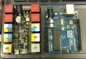
Figure 3. Me Uno Shield and Arduino Uno
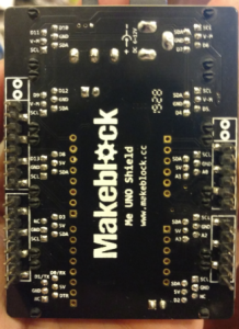
Figure 4. Me Uno Shield Back
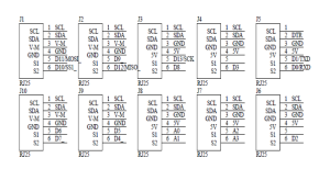
As shown above, the Me Uno Shield has 10 total RJ25 ports. Each port has SCL, SDA, power, ground, and 1-2 pins mapped to an arduino uno. The 4 red ports: 1, 2, 9, and 10 are supplied with 12v. Port 1 has PWM Pins (10 and 11) while port 2, 9, and 10 only have 1 PWM pin and a digital pin. We were worried that 2 PWM were needed to control stepper motors; however, after running some tests, and properly mapping out our pins on our software, we found that we were able to control a stepper motor on all red RJ25 ports.
Figure 5. Me Uno Shield 10 Port Pinouts
The image above is the Me Uno Shield 10 port pinouts. All this information is also shown on back of our Me Uno Shield. (Image provided for easier referencing).
Software
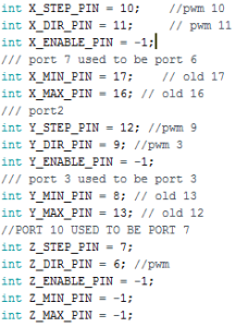
Figure 6. Me Uno Shield Pin Mapping
The Me Orion and Me Uno Shield did not have the same pin outs; therefore, on our Gcodeparser code, we were required to correctly map out our new pins for each stepper motor we will be using. We found that although we mapped our stepper motors properly on our arduino code, our GRemote (java) did not read our pin outs properly. In order to fix this, we had to evaluate the java code provided by the Gremote in order to understand why our stepper motors will not take any Gcode commands even though our pin outs on our arduino code was correct.
From our GCodeParser_Makeblock Orion folder, we had to navigate to two different files:
GRemoteFull → Source → GRemote.java
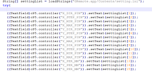
Figure 7. GRemote.java Line 1584 – 1598
In this GRemote.java file, we found that our stepper motors direction, steps, minimum, and maximum limiting switches for each stepper motor X-Y and servo Z pins were being taking from the “GRemote.app/contents/settings.ini.” We then decided to navigate to this location.
GRemoteFull → Java → bin → GRemote.app → Contents → Setting.ini
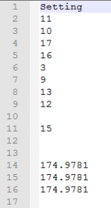
Figure 8. Settings from Me Orion
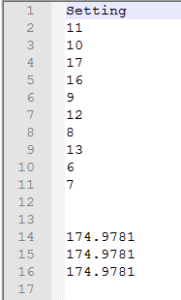
As we suspected, we found that the settings were defaulted to the pins from our Me Orion. 11, 10, 17, and 16 is our direction, step, minimum and maximum limiting switches for our X-Axis stepper motor. 3, 9, 13, and 12 is our direction, step, minimum and maximum limiting switches for our Y-Axis stepper motor. 15 is our direction for our Z servo. 174.9781 is our steps_per_mm for X, Y, and Z. After adjusting these pinouts to our Me Uno Shield, we obtain the following settings:
Figure 9. Settings from Me Uno Shield.
I was able to adjust our GcodeParser arduino code to allow our Z-axis to be treated as a stepper motors instead of a servo. After many attempts, and mapping my Z-Axis to Port 10 (Digital pin 6 and 7), I was able to control our Z-axis on Port 10. I had to map it properly on the GcodeParser arduino code, and adjust our GRemote settings file as shown in figure 8. In line 10 and 11, the Z-Axis stepper motor is mapped to Port 6 (direction) and Port 7 (step). Although only pin 6 is a PWM pin, as long as we mapped our direction of our stepper motors to the PWM pins, we were able to control our stepper motors without any problems. I then attempted to map our Z-Axis stepper motor to port 1, 2, and 9 on our Me Uno Shield. As long as I properly mapped the pins, I found that I was able to control the stepper motor using our GRemote in any 12V RJ25 ports.
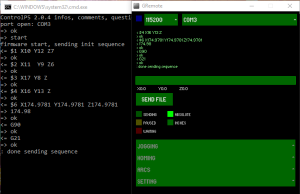
Figure 10. GRemote
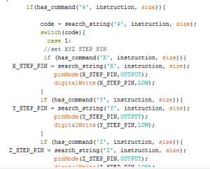
Now when we open our GRemote, we can see in Figure 10 on the left, each case ($) shows the correct pinouts according to our java and setting.ini file. For case $1, X10, Y12, and Z7 all represents our step pin. For case $2, X11, Y9, and Z6 represents our direction pin. For case $3, X17 and Y8 are our minimum limiting switch pins while Z is left empty because we have yet to implement a limiting switch pin for our Z-Axis stepper motor. For cae $4, X16 and Y13 are our maximum limiting switch pins while Z is left empty for the same reason stated prior. These cases can be found in our arduino process_string module. An example of case $1 is shown below.
Figure 11. Process_string Case $1 Example
Conclusion
Overall, being able to control more than two stepper motors was a breakthrough for us in this project. We are now able to have full control over more than two stepper motors which is crucial for our 3D SMD pick and place machine. We are now able to control X, Y and Z axis. In order to control our A axis, I will need to focus more on software to see how we can add another stepper motor to our GcodeParser. Now that are machine is able to communicate with our GRemote and accept GCode commands properly, we are one step closer to success of this project.
Reference
Me UNO Shield. (n.d.). Retrieved April 04, 2016, from http://learn.makeblock.com/me-uno-shield/

