Spring 2016 3D SMD: Verification Test – Vacuum Head Design
By: Christine Vu (Missions, Systems, and Test)
Table of Contents
Vacuum Head Test
To verify the size of the vacuum nozzle design, a test will be conducted to determine that the size of the vacuum provides sufficient pressure to pick up a SMT component.
Requirements
Section 5 Vacuum Head Design I
SMT component size 0402 shall be the smallest component that the pick and place SMD
machine can pick up.
Section 5.1
Vacuum system shall be able to pick up all SMT components as small as size 0402.
Section 5.1.1
Vacuum nozzle shall be smaller than 0.50 ± 0.05 mm.
Section 6 Vacuum Head Design II
ATmega32u4 chip shall be the heaviest component that the pick and place SMD machine can pick up.
Section 6.1
Vacuum suction pad shall be smaller than 0.4″ ± 0.01″.
Applicable Tools
| Equipment Type | Name (Brand) | Tolerance Level |
| Vaccuum Pressure Gauge | Actron CP7802 | +/- 2 psi |
Background
A trade-off study has been conducted to determine that there is enough vacuum pressure to pick up a heavy component without the attachment of a vacuum nozzle. The link is shown below, written by Henry Nguyen (Electronics & Control):
https://www.arxterra.com/spring-2016-3d-smd-vacuum-pump-trade-off-study-v2/
Because pressure is determined by force over an area, the vacuum nozzle size will affect the required pressure to pick up the heaviest component. If the vacuum nozzle is too large, then the smallest component, 0402 size, would go into the vacuum nozzle. Therefore, it was important to consider size parameters.The heaviest component was provided by ATechTop, who would need to place LM358MX. The test procedures below will verify that the vacuum nozzle size is sufficient to pick up this component.
Procedure
- Determine actual mass of desired 0402 SMT component. Record under SMT component mass column.
- With a T-connector, measure the pressure by connecting both ends of the vacuum tubing and pressure gauge. Fig. 1 is the photo of the vacuum pump.
- Turn on vacuum pump and measure pressure before attaching the solenoid valve. Record the value under corresponding measured pressure column.
- Measure pressure after attaching the solenoid valve. Record the value under the corresponding measured pressure column.
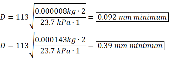
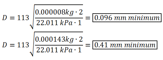
- Calculate the minimum required diameter using the equation below.
- Measure the diameter of the vacuum nozzle being used. Using the equation below, plug in the diameter size and calculate the maximum mass allowed.
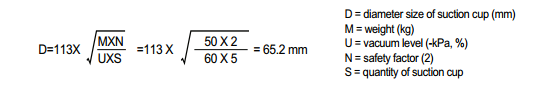
Equation 1. Obtained from (VMeca, n.d.)
Results
| SMT Component | SMT Component Mass (kg) | Vacuum Pressure behind (kPa) | Vacuum Pressure front (kPa) | Diameter behind(mm) | Diameter front (mm) |
| 0402 Resistor | 0.000008 | 23.7 | 22.01 | 0.092 | 0.096 |
| ATmega32u4 | 0.000143 | 23.7 | 22.01 | 0.39 | 0.41 |
Note: “Behind” and “Front” are indications of where the vacuum pressure was measured with respect to the solenoid valve.
Calculations
(A) T-connector to tubing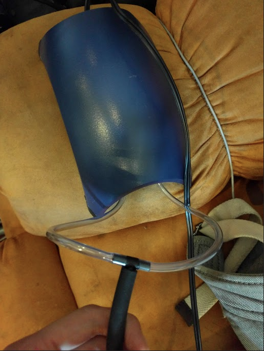
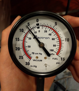
(B) Pressure Before
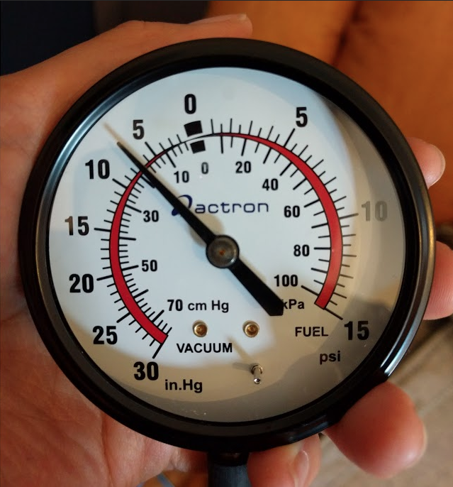
(C) Pressure After
Figure 1 – Test Equipment
Calculations
Conclusion
Our vacuum nozzle diameter indicates the minimum and values in order to pick up our desired SMT components. From calculations, there will be enough pressure for it to pick up the heaviest component, LM358MX, if we were to use a nozzle size of approximately 0.4 mm +/- 0.05mm. The solenoid valve measurements were used to check how much pressure loss there will be when operating the machine, which lost approximately 1 kPa.
To re-assure that the heaviest component is picked up, we will consider attaching a suction pad to cover more area and pick up the LM358MX SMT component. This concludes that our vacuum nozzle design is per requirement Section 5.1.1.
References
Datasheet for LM358MX
Mouser Electronics, n.d. Mouser Part #:512-LM358MX
Datasheet for SMT Component
Panasonic, 2015. Thick Film Chip Resistors.
URL: https://industrial.panasonic.com/cdbs/www-data/pdf/RDA0000/AOA0000C84.pdf