Spring 2016 3D SMD: X-Axis, Y-Axis, Z-Axis, A-Axis, and Origin Brackets
By Henry Nguyen (Electronics and Control)
Table of Contents
Introduction
For our 3D SMD pick and place machine, we were able to get most of our software for controlling our stepper motors done. The only thing left to do is to design and manufacture proper brackets for each of our stepper motors since we purchased 2 new geared stepper motors from Makeblock. The Makeblock geared stepper motors has different screw holes to hold the motor therefore we had to design new brackets and modify our existing brackets in order for it to work. I will be discussing our X,Y,Z, and A axis brackets as well as our origin placement bracket.
X-Axis
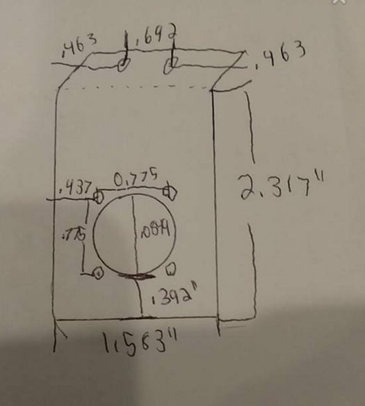
Figure 1. X-Axis Measurements
In order to manufacture our X-Axis bracket, I had to consider the dimensions of our geared stepper motors screw hole. I also considered the placement where our X-Axis bracket will need to be placed and design screw holes for its proper location. The diameter of the hole in which our stepper motor will be fitted is approximately .849 inches. Figure 1. shows a more descriptive measurement for everything that needs to be bend and drilled for our X-Axis braacket.
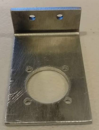
Figure 2. X-Axis Bracket
I was able to find a local metal shop nearby that was able to manufacture our desired X-Axis design. There are four screw holes placed around the the larger circle above. These measurements had to be exact in order for us to screw in our geared stepper motor properly.
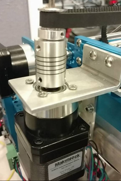
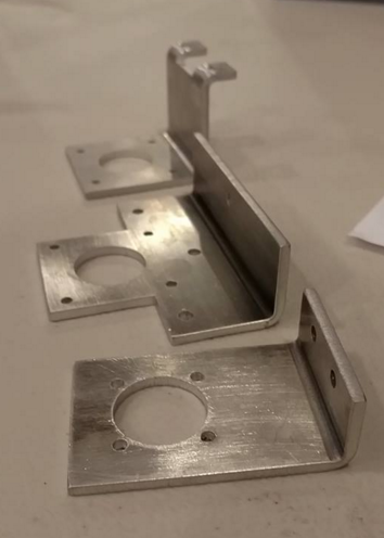
Figure 3. X-Axis Bracket Installed And Coupler Design
Figure 3 shows that I was able to successfully install our X-Axis brackets. The two screws on the top was able to attach properly our X-Axis. As we move our Y-Axis, our X-Axis geared stepper motor will be moving along with the machine.
Y-Axis
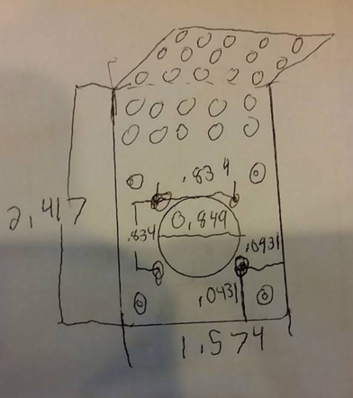
Figure 4. Y-Axis Measurements Figure 5. Y-Axis Bracket
For our Y-Axis geared stepper motor, I found that we could reuse our old X-Axis brackets from Makeblock that was meant for our non-geared stepper motors. This bracket is able to attach properly to our machine. The only problem is that we needed to drill holes to match our new geared stepper motors as shown in Figure 4 and Figure 5. I found that these holes were too close to the large circle therefore I had it professionally drilled in order to prevent any mistakes.
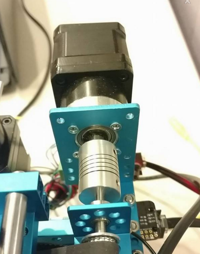
Figure 6. Y-Axis Bracket Installed
Figure 6 shows our Y-Axis geared stepper motor attached to our pick and place machine using the old brackets for our X-Axis. As we can see, there are 4 new screws that are screwed into our geared stepper motor. The coupler being used is a 8mm x 4mm coupler in order for these stepper motors to properly spin the 4mm rod on our Y-Axis.
Z-Axis
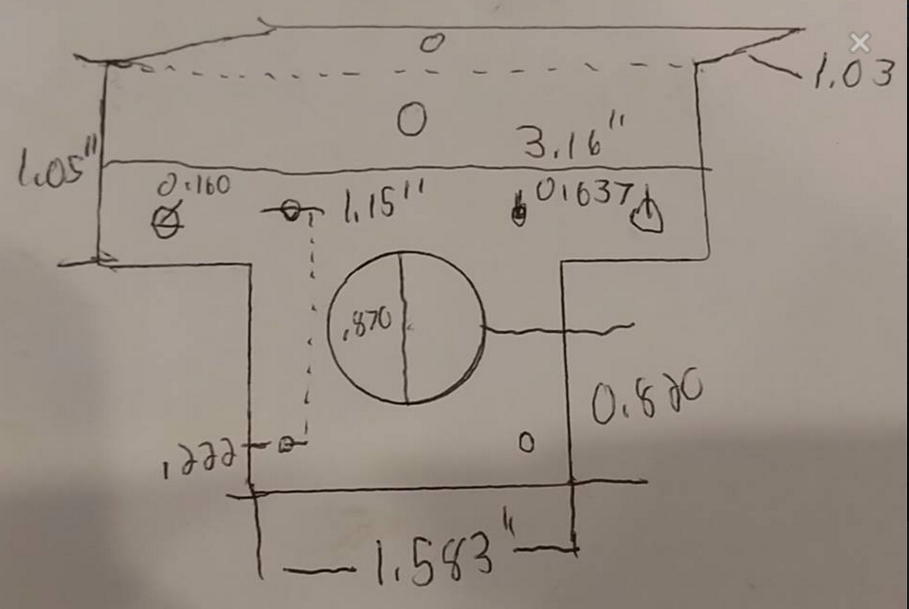
Figure 7. Z-Axis Measurements
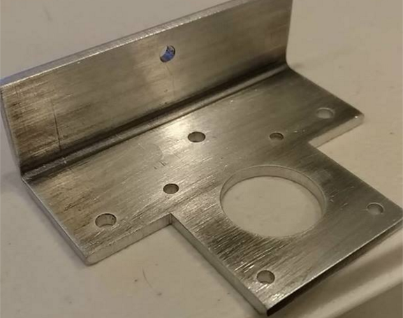
Figure 8. Z-Axis Bracket
Figure 7 is the design and measurements that I made for our Z-Axis. This time, we will be reusing our old stepper motors originally for our X and Y axis in order to control our Z-Axis thread drive. A unique design I added to this is that the bracket will extend our and bend 90 degrees. The purpose of this is shown in the image below.
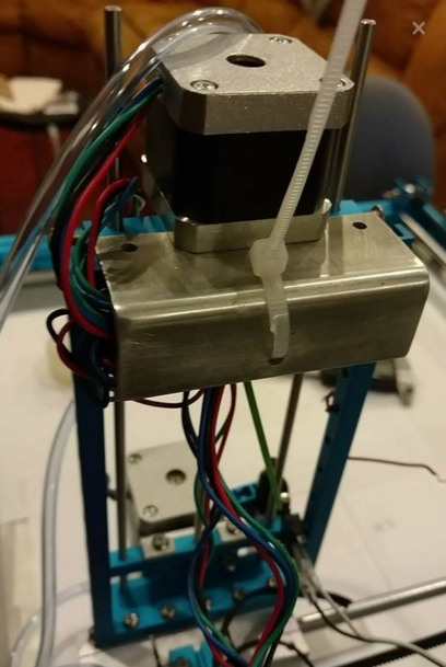
Figure 9. Z-Axis Cable Hiding
The reason for our Z-Axis bracket to extend is with 2 screws holes is to hide all the wires from our Z and A-axis stepper motors. As a result, I was able to hide the wires underneath this bracket and zip tie it in order to prevent these wires from being exposed. This is done for aesthetics of our machine as well as preventing any wires from being snagged or caught while our machine is running.
A-Axis
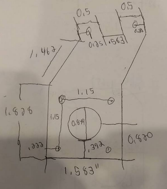
Figure 10. A-Axis Measurements
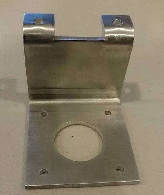
Figure 11. A-Axis Bracket
Figure 10 is my A-Axis design and measurement. This design should be able to allow our stepper motors to properly fit through the center hole as well as being screwed into the four screw holes. The proper measurements are shown in Figure 10. This bracket will also require 2 90 degree bends. In Figure 11, you can see the two screw holes on top. This will allow us to attach this bracket to our Z-Axis thread drive beam. This will allow our A-Axis stepper motor and bracket to move up and down when our Z-Axis is running. The importance of these 90 degree bends is to allow our stepper motor to be parallel with our machine which is crucial when picking and placing components accurately.
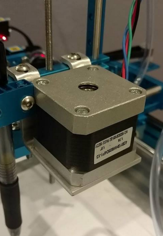
Figure 12. A-Axis Bracket Installed
Figure 12 shows our A-Axis stepper motor being installed onto our thread drive beam. The importance of this stepper motor is to allow rotation for our components in 45, 90, 135, and 180 degrees. Not all boards are created with the components being the same orientation every time therefore this stepper motor and bracket is crucial for the success and completion of a 3D SMD pick and place machine.
Origin Placement

Figure 13. Origin Placement Measurement
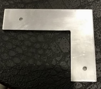
Figure 14. Origin Placement Bracket
Figure 13 is my design for our origin placement bracket. The dimensions of this is the same as the maximum size of free Eagle PCB of 4.0”x3.2”. Figure 14 is the actual bracket manufactured out of aluminum. The purpose of this bracket is so we will know where our origin is for our machine at all this. Another important use of this bracket is to ensure that when we place a PCB against this bracket, the PCB will be straight and oriented properly for the accuracy of our machine.
Conclusion
Overall, I was able to complete all the necessary brackets for our X, Y, Z, and A-Axis as well as the origin placement bracket. It is extremely important to note that getting proper measurements for all of these brackets is crucial. I had to design brackets that are specific to an exact item (stepper motors). If I did not get the measurements as accurate as possible, we would lose time and money. All of these brackets is extremely important to get designed and manufactured as soon as possible considering we are getting close to the end of the semester. Without these brackets we will not be able to properly run our machine, perform accuracy tests, and proceed with any progress.