Spring 2016: 3DoT David IR Lens Study
By: Kent Hayes (Electronics and Control)
Introduction:
The way we currently have our set up for the IR emitter/detector, the maximum range is about 3in. In order to meet this requirement, Kent researched and found a way to drastically increase the range by incorporating a lens. Kent previously purchased 11.3mm lenses for our IR emitters. He chose this size for the diameter based on the limited space with which we have to work. We were thinking of creating a tube and mounting it on the side of the PCB box (3in x 2in) that we were going to print. However, there was a change in the design of the legs which pushed our printing time over the 6hr limit so we will not be using the box, and will therefore be mounting it somewhere on the top plate.
Related requirements:
The subsystem requirement states the following:
- The maximum distance for the IR detector to detect a direct hit shall be 5 ft. This threshold is for when the IR emitter of the other robot is directly aligned with the IR detector, not when it is at an angle.
Lens options:
There are various types of lenses of which to choose from such as convex, concave, spherical, and compound.
- Convex: causes light rays to converge/concentrate into one spot
- Concave: causes light rays to diverge/spread out
- Spherical: less focused the wider the beam angle
- Compound: Increasing the focus while decreasing image distortion(aberration)
The lens that will work the best for our project is the convex lens since I wish to focus the IR beam as narrow as possible while increasing the range. There are different types of convex lenses as well. Among these are the more popular plano-convex and asymmetric double convex lenses because they produce the least amount of aberration. There is no notable difference between the two for this application, so I purchased the plano-convex.
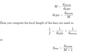
 I did further research online in order to preform calculations that would work with the measurements I do have thus far. The following image is of calculations I found on the magnification (M) in relation to the distance projected from the lens to a wall (dScreen)and the distance from the LED to the lens (dLED).
I followed the formula to calculate the magnification factor with the following values:
DScreen = 2m (Requirement for the IR emitter to be able to fire from 2m away)
DLED = 5mm (Random number just to do calculations)
With these I calculated the mag factor
M = 2000mm/5mm
M = 400
With the mag factor, I can then calculate the focal length of the tube.
Flens = 2000mm/(400+1)
Flens = 4.98mm
I also tried using a larger value for DLED to see what would happen to the focal length
M = 2000mm/10mm
M = 200
Flens = 2000mm/(200+1)
FLens = 9.95mm
These results suggest that my focal length should be between 5mm and 10mm.
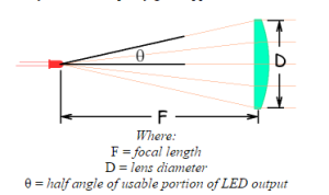
In order to get an exact value for the focal length, I did further research and found a helpful link that dealt with the focal length as well as the diameter of the lens. The following Image is of what I found:
 On the webpage I found this picture, it listed a formula for determining the minimum lens diameter. It is as follows:
D = 11.3mm lens diameter
F = focal length
Θ = 40 (half angle intensity of the current emitter we are using)
D > 2*F*tan(Θ)
11.3mm > 2 * F * tan(40)
F < 6.73 mm
Conclusion:
From the calculations made, we will be making a lens tube with a focal length less than 6.73mm with 11.3mm in diameter. In order to determine your focal length, you will need to use the half angle intensity of your own emitter and the diameter of the lense you have bought.
Resources:
Diameter/Focul Length Calculations | http://alumnus.caltech.edu/~leif/infratag/lens_choice.html
Magnification Calculations | http://physics.stackexchange.com/questions/146956/how-to-chose-right-lens-for-concentrating-ir-signal
Types of Lenses Summary | http://micro.magnet.fsu.edu/optics/lightandcolor/lenses.html

