Spring 2016: 3DoT David System Design
BY: Christopher Hirunthanakorn (Missions, Systems and Test Engineer)
Introduction:
The purpose of this blog post is to summarize the work done on the system design of the 3DoT David and show the final state of the system block diagram and system resource reports. At the end of this blog post, the reader should understand the different subsystems of the 3DoT David, how they interact with each other, and what parts were chosen for each subsystem. The interface definitions matrix is also covered here.
Table of Contents
System Block Diagram
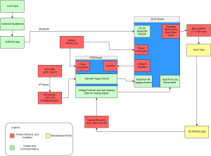
This system block diagram shows how all of the subsystems of the 3DoT David interact with each other. The major subsystems are the smartphone with ArxRobot App, 3DoT Board, PCB, battery, IR emitter, IR detector, micro motors, gear train, 3D printed legs, and flexible resistors. The interaction between the subsystems will be explained below.
The smartphone with the ArxRobot App is the subsystem that the user will be interfacing with the most. The user will be controlling the movement of the 3DoT David by using the directional pad controls on the app. Those inputs will be sent to the 3DoT Board via bluetooth. It will be processed by the Atmega 32u4 microprocessor that is on the 3DoT Board. If there is any telemetry, it would be sent back to the smartphone but that is not the case for the 3DoT David.
The 3DoT Board interacts with both the PCB and micro motors. It will be sending the control signal for the IR emitter and speaker to the PCB while receiving the outputs of the IR detector and flexible resistors after the processing is done on the PCB. The 3DoT Board also contains the Sparkfun dual motor driver TB6612FNG, which drives the micro motors. The board receives power from the battery.
The PCB contains the Schmitt trigger circuit which converts the analog output of the IR detector into a digital signal for the 3DoT Board to analyze using hysteresis. It also contains the circuitry for powering the IR emitter and speaker. It also contains the voltage follower and antialiasing filters to prepare the outputs from the flexible resistor sensors for the 3DoT Board to process in the motor phase control module of the software.
The IR emitter is controlled by the signal sent from the 3DoT Board and is powered via the circuitry on the PCB. It sends an IR signal in an attempt to tag the opposing robot. Both the IR emitter and IR detector make up the tagging system of the 3DoT David.
The micro motors are controlled by the Sparkfun dual motor driver TB6612FNG and move the gear train of the 3DoT David. The gear train is connected to the 3D printed legs and moves when the gear train moves. The movement of the 3D printed legs will move the entire 3DoT David and is used as the input of the flexible resistor sensors.
Interface Definitions:
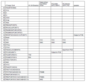
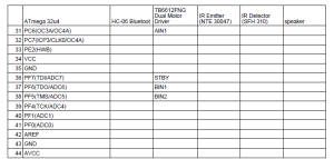
This interface definitions matrix shows how the various subsystems will be connected to the pins of the Atmega 32u4 microprocessor. The HC-06 bluetooth module will be connected to pins PD2 and PD3 which corresponds to the TX0 and RD0 pins of the bluetooth module. The Sparkfun dual motor driver TB6612FNG will be connected to pins PD7, PB5, PB6, PC6, PF7, PF6, and PF5, which corresponds to the PWMB, PWMA, AIN2, AIN1, STBY, BIN1, and BIN2 pins. The control signal for the IR emitter is connected to PD1 and that goes to the PCB. The IR detector output is connected to PD0. The speaker is connected to pin PB7.
System Resource Reports:
These are the system resource reports for the 3DoT David. The only major difference since the CDR is that the micro motor has been changed from the 3.7V 50K RPM coreless motor to the 900 RPM Micro Geared Motor.
Power Report:

This power report shows the updated values after changing from the 3.7 V 50K RPM coreless motor to the 900 RPM Micro Geared Motor.
Mass Report:
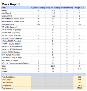
This mass report shows the measured mass of all components used to build the 3DoT David. It can be seen that the measured mass is 62% of the total expected and 50% of the project allocation. This was achieved by using the most efficient design for the 3D printed parts, which reduced the printing time and overall weight of the parts.
Cost Report:
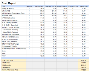
This cost report shows both the expected costs for parts that were generated during the PDR and the actual cost of the parts that were selected. All of these prices incorporate the shipping fees for those parts. The total actual price listed is assuming that all of the parts listed will need to be purchased and does not include the cost of the 3DoT Board.
