Spring 2016 3DOT Goliath, Making Laser Tag Possible: The Schmitt Trigger
By: Kevin Moran (Electronics and Control Engineer)
Since the analog output of the receiver is very noisy, my division manager suggested I use a Schmitt trigger which has 2 jobs:
- It reduces noise from the circuit through hysteresis, the time-based dependence of a system’s output on present and past inputs.
- It inverts the signal from the detector circuit and creates two thresholds-high and low. By changing resistor values we are able to control the high and low thresholds.
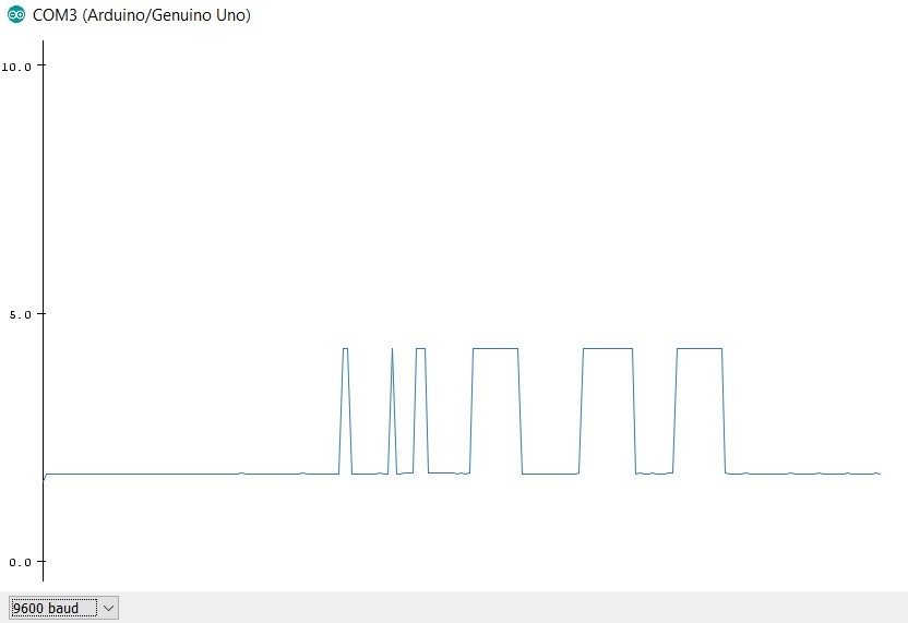
Below is the graph of a generic output using the Schmitt Trigger, as can be seen the signal is inverted, and the noise is relatively gone.
Now the challenge was selecting the correct Schmitt trigger that would work best with our receiver, after testing various resistor values, I made my choice between two sets of resistors.
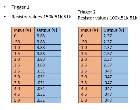
I decided to go with the resistor values from Trigger 1, because It has a larger gap between the high and the low thresholds. When tested with the Phototransistor it provides a low threshold closer to 0 voltage
All values were taken with multi meter while changing the input voltage
Note: The high and low threshold change when the Resistor value connecting the receiver is changed from 100k ohms to 2M ohms (I did this in order to increase the sensitivity of the receiver)
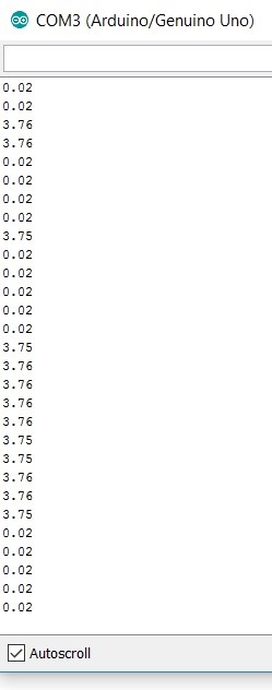
Testing with Arduino Monitor:
- When light is applied to the photo-transistor and the input is placed through the Schmitt trigger
- High Voltage= 3.76 V
- Low Voltage= 0.02 V
In order to make the phototransistor sensitive enough to be able to detect the IR light, I am using a 2 mega ohm resistor from the detector to the 5v supply
Both the high and low voltage thresholds are shown using the Serial Monitor
This is the result.
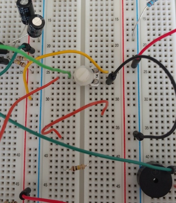
I also conducted a test on the Schmitt Trigger using a potentiometer
Components for this test:
10k potentiometer
LM358 Op-Amp
Resistors: 100k, 51k, 51k
Capacitors: 10 microF
Arduino Uno
The threshold between a high or low input from this test is 2.6V
As I varied the resistance in the potentiometer I obtained the graph provided in this slide
Based on this experiment I concluded that my Schmitt trigger was ready to be used alongside the photo-transistor.
Below is the result from this test using both the Arduino plotter and monitor
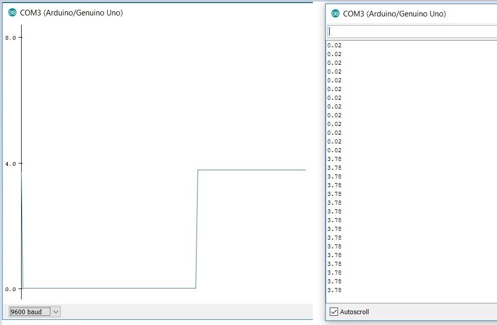
As can be seen again, a very clean signal that has only two outputs a low 0.02v and a high at 3.78v
Sources:
Jeffrey Cool: Division Manager
http://www.ti.com/lit/an/scea046/scea046.pdf
http://pcbheaven.com/wikipages/The_Schmitt_Trigger/