Spring 2016 3DOT Goliath Preliminary Design Documentation
By: Ayman Aljohani (Project Manager):
Table of Contents
MISSION OBJECTIVE:
Inspired by the German Goliath, 3DOT Goliath is designed utilizing 3DOT board, with the minimum 3-D printing time. The 3-DOT Goliath will battle 3DOT Spider, tag battle, utilizing optical transmission and receiving device. The 3DOT should be controlled via live camera, periscope, on an Android phone.
REQUIREMENTS & VERIFICATION:
1- The 3DOT Goliath will be tested Monday, May 9, 2016, which is the final day of the class.
Verification: Spring 2016 Final day
2- Level 1 requirements stipulate that the total cost of 3DOT Goliath should not exceed $90.
Project vs Product’s budget: To document the difference between development cost and final product cost, the 3DoT Goliath must create a Project Budget and a Product Budget.”
3- When receiving 3 tags, the rover is disabled.
4- Inspired by German Goliath, robots with tracks.
5- Print time less than 6 hours.
Verification: level 1 requirements were updated during last week meeting with the customer.
6- The tag game should be safe.
Verification: http://www.futureelectronics.com/en/optoelectronics/infrared-detector.aspx
DESIGN INNOVATION:
In order to have a robot that meets all level 1 requirements, the 3DOT Goliath would use IR sensors and transmitters. A prototype version of the project will be built using legos and Arduino to test the sensors and transmitter functionality. For a wider field view angle, a fisheye periscope will be added to the phone camera.
Step 1. Brainstorm:
Sensors and transmitters : IR
Control : Android phone
Step 2. Lateral Thinking:
Forced Relationship:
- Installing fisheye periscope – wider field view angle.
- Neck- extended to provide a high vantage point on the top.
Step 3. Solution :
The customer will be given two options:
1- Basic level 1 requirements design with the minimum basic attributes.
2- In order to meet budget requirements, optional attributes with additional costs will be provided to customer.
3- Development budget will allocated to test additional attributes that will be added to the project.
Mechanical Design
By: Jerry Lui (Manufacture)
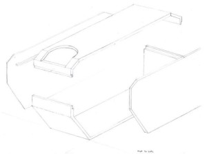
Here you can see the base and the top portions that were designed on Solidworks. I removed a segments of the body to help reduce of the volume used () as determined through the Solidworks mass properties feature. The removed sections were also shaped in a triangular cross section to help increase the integrity. Also, the corners were filleted using Conic Rho of .1, which helps to maintain the triangular edge whereas a normal fillet would had changed the dimensions of the cutout to be too rounded. The mounting of the gears and wheel are still being designed.
Product Breakdown Structure:
By: Tae Min Lee (Mission, Systems, and Testing Engineer)
The product breakdown structure will show the components we will using for the Goliath. The Goliath will be broken into 5 major components mobility system, controller, 3Dot Micro Controller, vision, and a battery. The mobility system will provide movement to the Goliath by using two motors that will connect to the gears to turn the tracks. The controller will be used to control the Goliath by using a Bluetooth module and an arxterra application. Next, the 3DOt Micro controller will be used to control the motors, laser/LED, and the sensor. Lastly, the vision of the Goliath will be using a periscope that will be attached to the android camera phone. This will allow us to see in the robot’s perspective as we control it through the axterra application.
Preliminary System Block Diagram :
By: Tae Min Lee (Mission, Systems, and Testing Engineer)
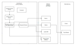
Before we start the design of the Goliath we have to breakdown the product. This will allow us to understand what kind of components that are needed to create the Goliath. In addition, this helps us map out the connections for each component of the miniature rover.
One of the customer’s requirement was to use Arxterra program and an android phone. This will allow us to see the view in the robot’s perspective using the phone’s camera. We will then communicate with the 3Dot Board via Bluetooth module to control the rover remotely.
The new 3Dot board contains a motor shield with a turbo booster to drive the DC motors. However, there is a limitation to the 3Dot board of adding various output components (laser, sensors). We will create a custom PCB to be able to add connections for the laser and the sensors to the 3Dot board.
verification: http://www.futureelectronics.com/en/optoelectronics/infrared-detector.aspx
Verification :https://acroname.com/articles/sharp-infrared-ranger-comparison
Lastly, the power supply will then be connected to the 3Dot board to power the motors, Bluetooth module, laser, and the sensors. These components will then be housed by the chassis, which will be designed and printed by the manufacturing engineer.
Electronics Control block diagram / Interface Matrix :
By:Kevin Moran (Electronics & Control engineer)
The block diagram shown above will show the electronic components we will be using on the Goliath. The blue tooth module will be able to send data to the Goliath to perform the basic operations in moving forward, backward, turning left, turning right, and shooting. We will be using two DC motors for our Goliath and a android phone to provide a via live video feed. All these components will be connected to the 3Dot Board and than powered by the battery.
Interface Matrix:
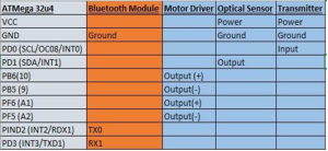
The interface matrix is shown above to show the pins we will be using on the 3Dot board.
For the optical sensor it will be connected to power and ground. The output of this signal will be sent to pin PD1 and sent to either a buzzer to indicate a sound that we got hit or an LED.
For the transmitter it will also be connected to power and ground. The input of the transmitter will be sent to pin Pd0 and sent to a lazer/LED for the emitter.
We will be controlling two motors for our Goliath, which requires four pins with each motor connected to power and ground. First motor will be assigned to pB6 and PB5 for power and ground. Second motor will be assigned to PF6 and PF5 for power and ground.
Level 2 requirements – Subsystem
- The rover will be controlled by two individual DC motors (3-5V)
Verification : http://www.ttelectricusa.com/
- A single charge of battery must power two DC motors, the camera, and the laser & sensors
- The rover will be controlled via Bluetooth using an Android Device.
Verification:http://arxterra.com/news-and-events/members/all-rovers/rover/
- An LED (or otherwise specified) will be used for a game of laser tag
- Laser receiver (on PCB) must be 3 inches off the ground, in order for successful game
- The 3DoT board will be used to control the rover
Unique Tasks:
Kevin Moran
- Define the requirements for motor once the definite rover specifications are provided by project manager and systems engineer.
- Using the power budget (provided by systems engineer) choose the correct batteries to power the rover for the specified amount of time (depending on laser game length).
- Provide the required integration for systems engineer to control rover via Bluetooth
- Design and implement the laser (LED or otherwise specified)
- Design and implement the laser sensors on PCB by
- Testing the circuit on PS SPICE
- Designing the circuit diagram on EAGLE CAD to provide manufacturing engineers with the codes for them to implement the PCB
- Place the laser sensor 3 inches off the ground to provide a fair game of laser tag
- Solder the 3DoT board in order to implement the rover along with its components such as the motor, laser, camera, and PCB receiver
3DoT Board Information (Digital Pins TBD):
o Micro-footprint 35 x 69 mm (1.38 x 1.73 inches)
o FREE Android and Apple iOS application software
o Pre-installed Arduino program – fully customized for your robot
o Integrated 3.7v Li-ion battery charger
o 5.0v Turbo Boost for driving DC motors
o TB6612FNG Dual DC Motor Driver
o Battery Level Sensor Circuit
o Both Android and iOS Bluetooth Modules available (purchased separately)
o Powered from a single CR123A 650mA rechargeable Li-ion battery (not included) with PTC protection, or bring-your-own Li-Ion battery (SparkFun compatible connector provided).
o 8 MIPS (Millions of Instructions Per Second) 2-Stage Pipelined AVR RISC Architecture Input/output Soldering Ports
o I2C soldering port compatible with SparkFun 9DOF Sensor Stick
o Two 3.7v Micro and Ultra-Micro Servo ports
o 10 Digital I/O ports and 4 Analog ports (of the Digital I/O ports)
o All digital logic powered from Low Dropout (LDO) 3.3v regulator with power and ground output ports provided
Level 2 requirements – Subsystem
By: Rickeisha Brown and Jerry Lui (Manufacturing)
- No Pan-tilt: must mimic German Goliath Rover
Verification : it was decided at during the meeting with the president.
- Proper placement of the periscope (1”) to the android phone for visual accuracy.
- Skeletonized body for weight reduction (< 2.87 lbs)
By: Jerry Lui (manufacturing )
- The camera on the phone must be able to see through the 1’’ periscope.
Verification: http://www.engadget.com/2013/04/24/samsung-galaxy-s-4-review/
- The phone,the sensor,and the transmitter must fit within the 3’’ body of the rover.
Verification: http://www.gsmarena.com/samsung_i9500_galaxy_s4-5125.php
Unique Tasks :
Rickeisha Brown:
- Design PCB Gerber file using Eagle CAD, while working alongside Control division in verifying we meet size requirements (≤ 1”) for our design, making sure we minimize costs.
- Solder IC components carefully on the PCB. If we get it right the first time, we do not need to order another PCB. Soldering IC components properly will be cost effective and time efficient.
- Locate a cost-efficient 3D printing company (contact manufacturing division manager) to print out 3D components.
Jerry Lui :
- Design and construct physical models or prototypes for dimensional references.
- 3D modeling of chassis using Solidworks, create a 3D model of the printable objects (chassis, LED housing).
- Assemble internal components, such as PCB, 3DoT, motors, etc. to be tested for fit, finish, and function.
- Test and verify that all moving objects on the rover are performing as expected.
Tasks Assignments:
Tae Min Lee – Systems
- Will create the product breakdown structure of the product (3Dot Goliath).
- Resource Report on the power and mass.
- Validation of Level 2 Requirement.
- Will learn C++ to program the Goliath using the Arudino IDE.
- Will research on how to use the Arxterra control panel.
- Verification and validation of level 1 and 2 requirements.
- Provide a block diagram of the connections to each component.
Kevin – Electronics
- Research on the type of sensors/lasers we will be using for the laser tag game.
- Provide specifications of the sensors and lasers.
- Perform trade off studies on the different type of sensors that can provide the maximum distance detection of the laser.
- Perform a prototype of the laser detection system.
- Provide a Fritzing diagram of the sensor and laser circuit.
Jerry Lui – Manufacture
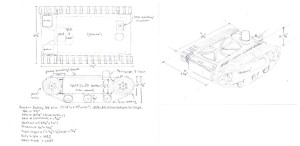
- Will create a 3D model of the 3Dot Goliath to provide an approximate dimensions for the robot.
- Will perform a 3D model and simulation using CAD.
Keisha – Manufacture
- Will layout where the components will be placed on the 3Dot Goliath.
- Will be responsible for cable management when connecting the components to the 3Dot board.
- Will purchase the PCB and perform the STM Stencil and re-flow of the board.
Preliminary Project Plan
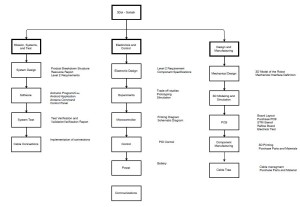
Work Breakdown Structure(WBS):
By: Ayman Aljohani (Project Manager)
Action items, assigned tasks, would be based on WBS and PPS.
Project Schedule:
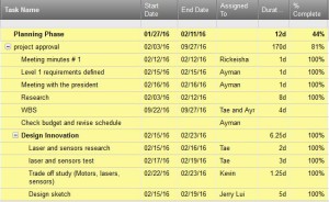
Top level schedule :
Highlighted in yellow is the top level schedule with assigned tasks and completion percentage
Water fall diagram:
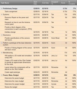
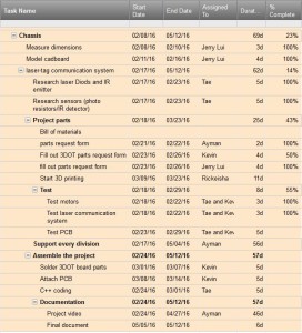
System/Subsystem Level Tasks:
Highlighted in orange is the subsystems schedule with assigned tasks and completion percentage.
Burn Down and Project percent completion :
The Blue curve shows the planned tasks percent completion against the Orange curve which is the actual tasks percent completion.
System resource reports:
By: Tae Lee (System Engineer):
Power budget report:
The chart above shows the amount of power the Goliath will be using for the project. We calculated the draw current of each component and took the total amount. The total draw current will help us determine the type of battery to choose for our Goliath. There will be a total power margin of + or – of 37mA. To make sure we had enough current supplied to each component we added the contingency of about 100mA just in case a component draws extra current from the battery.
Mass report:
This is the mass report of the different components that will be used for the preliminary design of the Goliath. The allocation of the mass was determined based on the weight of each component. For the contingency, we set it to be roughly 1 pound to be safe (total 2.5 pounds) with an expected weight of around 1.5 pounds. The weight of the chassis was determined through Solidworks mass properties function with ABS as the base material (density of 1.06g/cm^3).
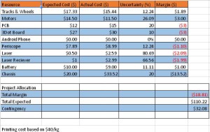
Cost estimate report:
The Cost Estimate Report shows the price breakdown for each component involved in building our Goliath Rover. Our customer is willing to pay up to $110.00 for the total cost of the design. It is our job as engineers to satisfy these financials limitations. Given that our Goliath design is “small” in size, including the 3Dot board, 3D printing & tracks and wheels, our overall cost will decrease. Please refer to our Cost Estimate Report for specific part costs.

