Spring 2016: 3DoT Spider-Bot Preliminary Design Document.
By: Omar Mouline (Project Manager), Christopher Hirunthanakorn (Missions, Systems and Test Engineer), Kent Hayes (Electronics and Control Engineer), Andrew Saprid (Manufacturing and Design Engineer)
Table of Contents
The 3DoT Spider team:
Omar Mouline (Project Manager)
Christopher Hirunthanakorn (Missions, Systems and Test Engineer)
Kent Hayes (Electronics and Control Engineer)
Andrew Saprid (Manufacturing and Design Engineer)
Preliminary Design Document.
Objective:
The customer wants a feasibility demonstration of a 3DoT Board, from ArxterraTM, for a low cost, DIY project. The idea behind the 3D of Things (3DoT) is for the DIY community to construct small-scale and quick-production robots. The project must be able to perform an interactive game with other projects. The overall result must be professionally presentable (as a promotional video) for The College of Electrical Engineering and ArxterraTM.
Requirements:
Program requirement:
- As a senior design project for Spring 2016, the project shall be completed by May 13th, 2016 Monday, May 9, 2016 2:45PM – 4:45PM (Final day) on the linoleum floor of ECS315 at CSULB.http://web.csulb.edu/depts/enrollment/registration/final_exam/spring_chart.html
- As a senior design project for Spring 2016, Documentation of the 3Dot Spider-bot shall be completed by the 25th of April http://web.csulb.edu/~hill/ee400d/Syllabus.pdf
Project Requirement:
- The project shall be Cam-based robot that demonstrates the capability of the new 3DoT micro-controller for DIY hobbyists.
- The 3DoT Spider project shall be a low cost project with a budget that does not exceed $79.95, which include the cost for the 3D printing material, PCB, battery, and other components.
- To document the difference between development cost and final product cost, the 3DoT spider project must create a Project Budget and a Product Budget
- For a Quick Production, the project has been restricted to six hours of total printing time with a 2 hours limit for each single print.
- The competing robots shall use an on-board optical transmitter and receiving system to simulate a game of tag.
- The orientation of the transmitter and sensors shall be parallel to ground. Since both teams are still designing the robots, the height of the sensors and transmitters is temporary set to 3 inches above ground until both teams finalize this requirement .
System requirements:
- The 3DoT Spider shall utilize the Bluetooth module on the 3DoT board in order to receive commands from the Arxterra Control Panel (via the Android Application).
- The 3DoT Spider shall use a single 3.7V Lithium-ion battery or a 3.7V Lithium-ion Polymer (LIPO) battery to power the 3DoT board.
- The 3DoT Spider shall operate for three rounds of “Tag”. One round of “Tag” ends when a robot has been “hit” three times and is disabled. This may last for 10 to 15 minutes.
- The 3DoT Spider shall use a micro servo for head rotation and a motor for the Cam-based walking movements of the robot.
- The 3DoT Spider shall use an on-board optical transmitter and receiving system to simulate a game of “Tag”.
- The type of optical transmitter and receiving system is still being researched.
- The 3DoT Spider shall be disabled after being tagged three times to signify the end of the “Tag” game.
- The 3DoT Spider shall incorporate 3D printed parts for the legs, body, or head. This follows from the level 1 requirement dictating the limit on 3D printing times.
- The 3DoT Spider shall include an external PCB that uses an op-amp comparator with hysteresis to perform the analog to digital conversion of the sensor inputs. This external PCB shall also provide the connections from the 3DoT microcontroller to its peripherals such as the optical transmitter, servo, and motor.
Subsystem requirements:
- The servo and motor shall operate in between the supply voltage of 3.7V-5.0V, be able to rotate 360 degrees continuously, and be priced reasonably in order to stay within our budget
- .The spider-bot shall be made of plastic light-weight material in order to save battery power and strong to hold the its weight.
- The laser shall be built on the head 3 inches from the surface to the top of the spider.
- The spider-bot shall have six legs to operate its course to battle robots.
Design innovation
Following the same process we did on our creativity presentation, we considered additional problems where we applied the same principle to find solutions.
The two main problems we have to consider are the printing time for the parts of the robot and the limited budget. We have a proposed solution for both and they will be modified upon customer feedback. For the printing time, we will create a design for the legs and chassis that use the minimal amount of material. When it come to the cost, we will use the most cost effective components.
https://docs.google.com/presentation/d/16sMUoAAnMPPTLNCC8_uLHyztSfAgli1p8mzOXfZE3bU/edit?usp=sharing
System/Subsystem Design:
Product Breakdown Structure:
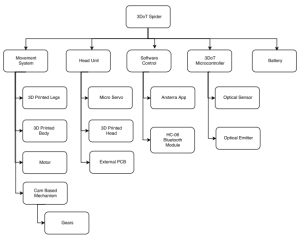
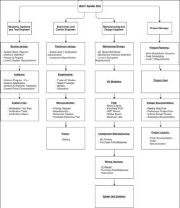
This product breakdown structure outlines the major components of the 3DoT Spider. The 3DoT Spider can be broken down into the battery, 3DoT microcontroller, legs, and chassis. The battery will be providing power for the whole system. The 3DoT microcontroller will be controlling the motor, micro servo, optical transmitter, and sensor. The legs includes the design of the 3D printed legs and the Cam-based movement system. The chassis includes the design of the head and body of the 3DoT Spider where all of the components will be enclosed in.
Electronic System Design:
System Block Diagram:
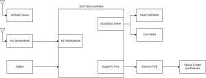
This system block diagram shows how the different components of the Spiderbot interact with each other. The android device uses the Arxterra Control Panel to send control commands through bluetooth to the bluetooth module on the 3DoT microcontroller. The 3DoT microcontroller will process those commands and send out the corresponding instructions to the motors, optical emitter, and detector. The battery provides power for the 3DoT microcontroller, which is then distributed to all other components.
Interface Definition:
Mechanical design:
First step was to analyze the Cam-Based movement of the Hex-Bug. It was done as a power point presentation to explain to the team members: Cam-Based Power Point Presentation
Building Parts Process:
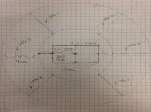
This is the first rough draft of the 3Dot Spider. Each leg is placed symmetrically to each other to ensure stability and be able to carry its weight. The original hexbug spider is too small for the 3Dot board to fit inside the head. The method is to resize the model given to make sure the 3Dot board fits inside the head. This is the 2nd rough draft of the initial base design of the 3Dot Spider. The new 3Dot board measurements are 3 inches in length and 2 inches in width. Adjustments were made to make sure the board fits into the base of the Spider.
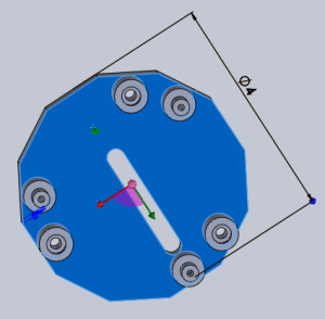
This is the base design of the 3Dot Spider-bot on SolidWorks. The base is designed to fit the PCB inside the head of the 3Dot Spider. The shape of the base design is a circle with a diameter of 4 cm from the center of the PCB to make the decrease the cost and lower printing time. This is to make sure the PCB fits inside the 3Dot Spider-bot and make it invisible from a human eye.
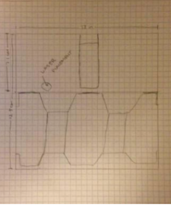
This is a rough sketch of the head of the 3Dot Spider. The laser will be placed 3 inches, or approximately 7.62 cm from the surface to the top of the spider. Laser placement will be an issue because of the length of the head is 12.5 cm, but the surface is not taken into account. From the surface to of the spider to the bottom is 5.5 cm measured approximately. From our studies, the laser should be better put on the head because the head is rotating 360 degrees otherwise it will be placed between the leg of the spiders which will make it an obstacle to the spider’s walk.
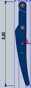
The leg design of the 3Dot Spider-bot is made from Solidworks. The length of the leg is 5.5 cm. The width of the original Hexbug Spider measures 0.8cm width on the top, 5.5cm in length, and 0.3cm width on the bottom. The reason why the leg is slanted is to ensure stability as it walks and support its weight.
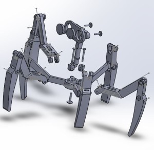
Exploded View
The exploded view is showing Most of the important parts for the 3DoT David which includes: Tibia, Femur, joints, and Cam based.
Unique Task descriptions:
Christopher Hirunthanakorn
- Perform trade-off study with 3DoT Goliath team to finalize what optical transmitter and sensor to use for the tag game. (1 week)
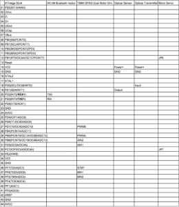
- Create Fritzing diagram for the circuitry needed for the 3DoT Spiderbot with complete wiring and pin-outs from the microcontroller. (2 weeks)
- Create and test custom Arxterra Control Application used on an Android device for controlling the 3DoT Spiderbot. (6 weeks)
- Write code for the 3DoT microcontroller to decode instructions received from the Arxterra Control Panel. (6 weeks)
Kent Hayes
- Consult the Goliath team’s Electronics and Control division in order to determine what type of optical transmitter and receiver is being used for the game of “tag”. (1 week)
- Work on simulations for servo/motor control through the arduino uno board until the new 3DoT board is shipped (2 weeks)
- Create a Frizting diagram from the interface matrix (2 weeks)
- After determining the transmitter/receiver, order the parts and conduct tests on battery life with all the components to analyze how long the battery can run with its 1000mAh rating and write a document explaining the results. (3~4weeks)
- Create an electrical schematic for the pcb layout using eagle CAD (2~3 weeks)
- Work with the systems engineer to write software subroutines and functions to read data from the optical transmitter/receiver to let the players know their bot has been tagged. (3~4 weeks)
Andrew Saprid
- Create a complete 3D model of the 3Dot Spider by using Solidworks. Once completed, it will be sent to 3d print shop for printing parts. (4 weeks)
- Run simulations and tests for the complete 3D model in Solidworks. ( 2 weeks)
- Perform a stress test on the leg design to determine the maximum stress level. (1 week)
- Research cost-efficient and resilient types of material by doing a trade-off study. The study will do a comparison of types of material that would best fit the Spider in terms of strength, weight and price (1 week)
- Fabricate the PCB designed in EAGLECAD (2 weeks).
Preliminary Project Plan
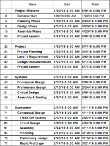
Work Breakdown Structure (WBS) Chart
By Omar Mouline, Project Manager
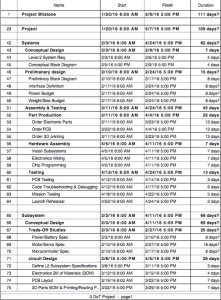
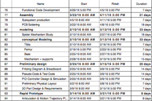
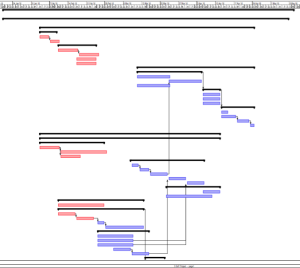
Project Schedule
By Omar Mouline, Project Manager
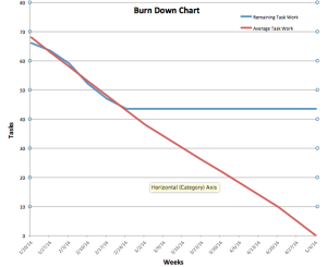
Using the Simple Robot Project Libre as a reference to organize my schedule, since The Simple Robot Project had a well defined tasks.I also used the Project Libre tasks to create the Burn Down Chart.
Top Level Schedule
System/Subsystem Level Tasks
Burn Down and Project Percent Completion
System Resource Reports
By Christopher Hirunthanakorn (Missions, Systems and Test Engineer)
Power Report
This power report is an initial estimation of the amount of power the 3DoT Spider will use. The values for each component were obtained from the datasheets if possible. When the datasheet did not have that information, a reasonable estimate or calculation was used instead. For example, the information on the current used for the 3DoT Board is taken from page 383 of the ATmega 32u4 datasheet (https://drive.google.com/file/d/0B9ONhnOsqgWdUjNjTGI5bExaZHc/view?usp=sharing). While it is not explicitly stated what the minimum, maximum, and average current draw are for the ATmega 32u4, a reasonable estimate was made to obtain those values.
The average current and expected power columns required some calculations in the case that it was not on the datasheet. The average current was calculated by taking the average of the minimum and maximum currents ((Minimum + Maximum)/2). The expected power was calculated by multiplying the rated voltage by the average current. For the most part, only the micro servo and 3DoT board needed this calculation.
The justification for the allocation of 2.5 watts for power is that it is a reasonable amount of power for a small robot. Assuming that most components operate at 5 volts, the total average current draw of those components would be around 800 mA. The 3DoT Spider should use less power than that even when including the total margin, which can be seen in the report.
Mass Report
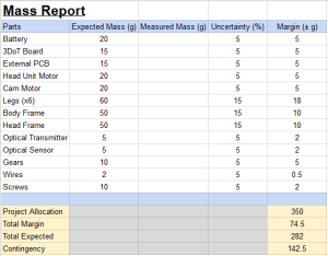
This mass report is an initial estimation of the total mass of the 3DoT Spider. All values are approximated except for the motor and micro servo, which are taken from their corresponding datasheets. It should be noted that the mass for the legs is the sum of all six legs. It is approximated that each leg will weigh 10 grams with a margin of + or – 3 grams. Those values were determined based on the weight of the first prototype leg. It weighed 15 grams and is much larger than the current version.
The justification for allocating 350 grams for the mass of the 3DoT Spider is that it is slightly above the total expected mass. It allows for quite a bit of contingency in the case that certain components such as the body or head frames end up being larger than expected. It is very likely that the project allocation will decrease as more accurate approximations for the 3D printed parts are obtained because the 3DoT Spider will be designed to be as small as possible.
Project Cost Estimate
By Christopher Hirunthanakorn (Missions, Systems and Test Engineer)
Cost Report
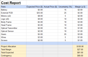
This project cost report is an initial estimation of the total cost of building the 3DoT Spider. All of the expected prices listed are rough approximations or the average price for that type of component. The customer wanted a low cost robot that would cost $79.99, however the estimated total cost is $81. The total cost may decrease once components have been finalized but it is more realistic to budget for the margins and contingencies as well. In the case the actual price includes the total margin value, it will be $108, which is already $28 over the desired cost. Therefore, we propose a project allocation of $120, which will be discussed with the customer.

