Spring 2016 A-TeChToP Central Sensor Suite Sensor Post #1
Stephen Cortez (Electronics Engineer)
Introduction
For the Spring 2016 semester, the A-TeChToP project was divided into two portions: the Central Sensor Suite (CSS) and the Seizure Watch (SW). This post will discuss the detailed instructions to wire, test, and program the sensors chosen for the CSS portion. First, there are five sensors in total that are used in this project which cover temperature, orientation, electrocardiography, pulse, and blood oxygen.
Table of Contents
Parts Chosen
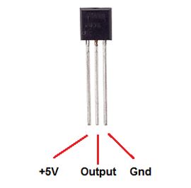
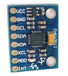
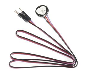
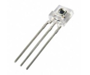
The actual parts chosen for each of the sensor areas mentioned above are the LM34 temperature sensor, the GY-521 MPU6050 Accelerometer-Gyroscope Combo Board, a custom-made ECG (made with various components that will be listed later), the SparkFun Pulse Sensor Amped SEN-11574, and a custom-made blood oximeter using a TSL235R Light-to-Frequency Converter and LEDs. All of these sensors can be seen in the figures below and here are links to their respective datasheets (note that the datasheet for the GY-521 is for the motion processing unit (MPU) series category that it falls under. Also, ECG component datasheets will be given later):
LM34: http://www.ti.com/lit/ds/symlink/lm34.pdf [1]
GY-521: https://www.cdiweb.com/datasheets/invensense/PS-MPU-6000A.pdf [2]
Pulse: https://upverter.com/datasheet/a9cbdf5498506868cf8115c748860f5bf7099583.pdf [3]
TSL235R: https://www.sparkfun.com/datasheets/Sensors/Imaging/TSL235R-LF.pdf [4]
Fig 1. LM34 Temperature Sensor
Fig 2. GY-521 Accel Gyro Combo Board
Fig 3. SparkFun Pulse Sensor Amped
Fig 4. TSL235R Light-to-Frequency Converter
Microcontroller
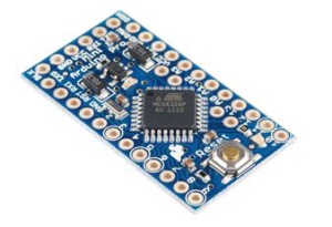
In order to program all of these components, an Arduino Pro Mini microcontroller (MCU) as seen in Figure 5 will be used along with the Arduino IDE software. It is recommended to download the most recent version of Arduino IDE (or at least version 1.6.7.0) in order to have access to the Serial Plotter tool for testing: https://www.arduino.cc/en/Main/Software [5]. An FTDI serial cable will be needed to connect to the Pro Mini and program it. This particular FTDI programmer requires a USB Mini-b (5 pin) type cable to make a proper connection. Note that both the Arduino Pro Mini and FTDI programmer can come in either 3V or 5V versions, so verify that you get both of the same kind. For this project, the 5V MCU and 5V FTDI were used.
Here is a link to a description about the Arduino Pro Mini: https://www.arduino.cc/en/Main/arduinoBoardProMini [6].
Figure 5. Arduino Pro Mini MCU
In order to evenly divide the sensors, the rest of this blog post will now discuss the sensors that do not require a custom designed circuit while the other custom sensors will be discussed in part two.
Temperature Sensor
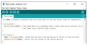
First, the LM34 sensor is a simple component that requires minor coding to receive a signal and then some simple conversion calculations in order to derive the temperature readings in units of Fahrenheit. First, connection the appropriate Vcc and GND pins to a 5V source and Ground respectively. Then, connect the output pin directly to any analog pin on the Arduino Pro Mini you like except for pins A4 or A5 (these are pins used for I2C communication and must be reserved for the GY-521). Note that if the LM34 becomes hot soon after making these connections and being powered, then you most likely have the Vcc and GND pins wired opposite to the correct configuration. Immediately disconnect the component and wire it correctly to avoid damaging it. The pin A6 was chosen to read the temperature value. Next, open up Arduino IDE and enter the following simple code (comments are included although it would be useful to practice using this program since it can be used for all Arduino boards). This code is intended to simply test that values can be read from your LM34 sensor, but it is the basis for reading other sensors as well:
Figure 6. LM34 Raw Data Reading Code
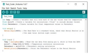
Check to see that the values in the Serial Monitor (found under the “Tools” tab or click the top right magnifying glass button) are relatively consistent and increase when you touch the sensor and decrease when you release it. These values are in millivolts and outputted to be proportional to the actual temperature. If these are not the results you are seeing, verify your LM34 connections and ensure that the analog pin (A6) in the code is the same pin you have the output of the LM34 connected directly to. Next, add some calculation lines to the code in order to convert the raw readings into Fahrenheit temperature readings and view them on the Serial Monitor. Once this is done, use the same finger touch test to verify that that temperature increases and decreases appropriately, and that the readings seem proper for the room that you are in. You should also able to place the sensor underneath your arm in order to try to measure actual body temperature, in which case you should see values from 95 to 98 degrees Fahrenheit, although the results may be slightly off.
Figure 7. LM34 Temperature Output Code in Fahrenheit
In order to obtain accurate temperature readings, the LM34 will be placed in the under arm of the child wearing the device. This should conclude the wiring, testing, and code for the LM34. Next, the Pulse Sensor Amped will be discussed.
Pulse Sensor
The model ordered by the CSS team consisted of the sensor with three wires stemming from it and each wire was color coded to match its specific purpose. The wires were Red, Black, and Purple and represented Vcc, GND, and output respectively. Connect the device to a 3V or 5V source, Ground, and any analog pin that is not in use (again, not A4 or A5) respectively. Once powered, a green light should be blinking on the head of the sensor, indicating that it is powered and functioning. The code for the device can be found on SparkFun through the following link: https://www.sparkfun.com/products/11574 [7]. From this link, help can be found about the code with explanations, walkthroughs, and wiring as well as the code itself. For the CSS, analog pin A2 will be used. The files included in the given pulse sensor code consist of ultimately four ‘.ino’ (Arduino IDE format) files named “AllSerialHandling”, “Interrupt”, “PulseSensorAmped_Arduino_1dot4”, and “Timer_Interrupt_Notes”. If you click on the “Interrupt” file first, then all four should open up in the same window under different tabs. Depending on how you integrate the code into your telemetry, leaving the four files tabulated may be better than combining all of them into one IDE sketch, or vice versa.
Figure 8. Tabs of Pulse Sensor Code Files
In order to control how the data from the pulse sensor is outputted to the Serial Monitor, click on the “AllSerialHandling” tab. In this tab, the void function named “serialOutput” determines how the information is outputted by changing the variable “serialVisible” equal to TRUE or FALSE. TRUE will output simple numerical results while FALSE will output a visual trick where the ‘-‘ symbol prints in real time on the Serial Monitor in the shape of a pulse. Each time a pulse is detected, a small curve is created by these symbols as they are printed and when there is no pulse they print out as a constant line.
Accelerometer
Next, the GY-521 sensor will be covered. Based on the image seen in Figure 2, this sensor has pins Vcc, GND, SCL, SDA, XCL, XDA, AD0, and INT. Despite having eight pins, only five need to be connected for the purposes of the CSS project. Connect Vcc to 3V or 5V, GND to Ground, SCL to analog pin A5, SDA to analog pin A4, and AD0 to Ground. If for the purposes of your project the use of two MPUs are needed, pin AD0 on the breakout board defines the address of the device. Since I2C communicates through a single bus, it reads addresses as a single line of code, which can be troublesome if there is more than one address causing interfering data. Therefore, AD0 connected to Ground defines the address of the corresponding device to 0x68 while AD0 connected to High or Vcc defines the address of the corresponding device to 0x69, allowing communication through a single Arduino’s I2C with multiple devices. This means that the single GY-521 MPU used here has AD0 connected to Ground and the device address is set to 0x68. I2C communication is the reason pins A4 and A5 needed to be reserved for this device. On most Arduinos, these two analog pins allow for I2C communication with specific devices, most often being MPUs. Therefore, the raw data from the GY-521 is transferred from the SCL and SDA pins to A5 and A4, which is a process that will not work with any other analog, or digital for that matter, pins. It is possible to check the connection of the GY-521 and verify that it is being recognized at the correct address. This is done by using the I2C scanner code, given in the following link, which will output to the Serial Monitor if a device is successfully connected and if it’s address is 0x68 or 0x69: http://playground.arduino.cc/Main/I2cScanner [8].
Once the proper connections are made, the following library will need to be downloaded from GitHub: https://github.com/janaka/Gy521-Dev-Kit [9]. This library was written specifically for the GY-521 and can be uploaded immediately to the Arduino board with positive results. Simply click on the “Download ZIP” button on the right and then extract those files into your “Arduino” folder. Some initialization and calibration is automatically done through the code, so ensure that the GY-521 is set on a flat surface once you begin. The angles will all print on their own lines and be denoted by some text to indicate what value they represent. Move the GY-521 sensor around and verify that the angles observed are correct to the orientation using the printed axes on the top of the device itself. Although this is a complicated way to use the GY-521, it was favored by the CSS group since it contained the majority of the complex angle calculations necessary. That does mean though that there are other ways to communicate with the GY-521 device with other libraries, but they may require more work. An additional feature that may serve interesting purposes is that the GY-521 device has a temperature sensor built into it, which can be used for whatever reasons found appropriate.
Conclusion
This concludes the first blogpost about the sensors for the CSS project, where wiring, testing, and code specifics are covered as well as direct resources for each sensor. The second blogpost for CSS sensors will cover the custom made sensors: the ECG and the blood oximeter.

