Spring 2016 RoFi: Mechanical Design Rev.1
Christopher Andelin (Project Manager)
Mario Ramirez (Systems Engineer)
Qui Du (Manufacturing Engineer)
Andrew Laqui (Electronics and Controls Engineer)
Henry Ruff (Electronics and Controls Engineer)
Table of Contents
Mechanical Design
Qui Du (Manufacturing Engineer)
Objectives for this Design
RoFi is the fifth prototype from Project Biped. It has twelve degrees of freedom and can walk around while avoiding obstacles using an ultrasonic range sensor. A small Android phone in RoFi’s head provides the brains, an Arduino Uno provides the hardware interface, and batteries to power the servos. By reading the “RoFi- Next Generation Head- DAREL” project designed by Mike Pluma, I think this is a good design for our Rofi; therefore, I used this design for our RoFi head.
Body base design planning
Sources:
https://www.adafruit.com/datasheets/arduino_hole_dimensions.pdf
http://www.hobbyking.com/hobbyking/store/__9493__Turnigy_1300mAh_3S_30C_Lipo_Pack.html
http://www.seeedstudio.com/wiki/index.php?title=Ultra_Sonic_range_measurement_module
SolidWorks Modeling Design
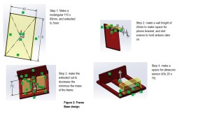
Step 1: determine dimensions of the body base
Long dimension of body base ≥ width dimension of phone base + (2*width dimention of battery) + width dimension of ultrasonic sensor +dimensions of two walls.
Long dimension of body base ≥ 20 + (2*34) + 15 + 10 = 109; however, we need space for wires and extra items, the long dimension of body base is 114 mm.
Width of body base ≥ long dimension of battery = 78, since the long dimension of a battery has a largest scale to be place in the body base; therefore I round width dimension of body base to 80 mm.
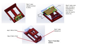
Step 2: SolidWorks model for body base
Note: plane2 was added to make an extend space (5mm) for the phone bracket.
Drawing diagram
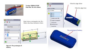
Step 3: SolidWorks Prototype of batteries
For our projects, the battery type is the last item to be chosen, however, to make my body base design more realistic, I chose the battery type from last semester as an prototype of this design.
Battery Turnigy 1300Ah 3S 30C. Dimensions: 78 x 34 x 23mm
Source: http://www.hobbyking.com/hobbyking/store/__9493__Turnigy_1300mAh_3S_30C_Lipo_Pack.html
Step 4: SolidWorks prototype for Arduino Mega
Arduino Uno has dimensions: 68.6 x 53.3 x 2mm
Source: https://www.adafruit.com/datasheets/arduino_hole_dimensions.pdf
Step 5: SolidWorks prototype for Ultrasonic Sensor
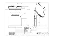
Step 6: Make a new prototype bracket for Android phone
In the last blog post (https://www.arxterra.com/spring-2016-rofi-preliminary-design-documentation/), I designed brackets that support a phone in either vertical or horizontal orientations; therefore, I made a bracket from 2 pieces that can be adjustable to fit with width dimension of the phone. Because my project just needs the phone to be placed in the vertical orientation; therefore, in this new design, I make a one piece bracket for the android phone.
Drawing diagram
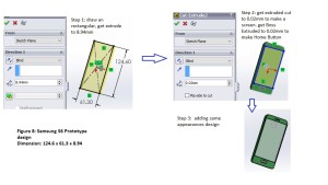
Step 7: Make a prototype of an Android phone
Step 8: Assembly Modeling and Exploded View
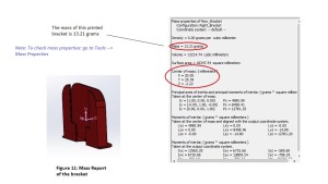
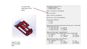
Mass Reports
By using the Mass Properties feature, I can determine the mass of the designs before they are printed.


