Spring 2016 RoFi: Finalized Fritzing Diagram, PCB Design, Alternative Arduinos, and Custom Eagle Components
Christopher Andelin (Project Manager)
Mario Ramirez (Systems Engineer)
Qui Du (Manufacturing Engineer)
Andrew Laqui (Electronics and Controls Engineer)
Henry Ruff (Electronics and Controls Engineer)
Table of Contents
Finalized Fritzing Diagram
By Andrew Laqui (Electronics and Controls Engineer)
The Fritzing software, found here , allowsa physical breadboard design to be created digitally. By designing a digital version, the beginning PCB designs can begin. One difficulty with using the free software is that the library does not have all the parts needed for many designs. Using Google, many of the parts required were found with Github.
Here are links to the Fritzing libraries for RoFi:
https://github.com/adafruit/Fritzing-Library (If using the Adafruit Servo Driver)
https://github.com/RafaGS/Fritzing (For the Bluetooth Module HC-06 and Accelerometer/Gyroscope MPU-6050)
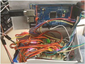
The image below shows what the PCB will be replacing. Just having twelve servos without any of the other components creates quite a messy board; especially on the Arduino MEGA, wires would often come out and cause a servo to stop working. The new PCB allows the servos to be easily plugged in while keeping the wires from becoming tangled.
PCB Design
By Andrew Laqui and Henry Ruff (Electronics and Controls Engineer)
Due to the requirement to use a smaller Arduino microcontroller than the Arduino MEGA, we originally thought that we had to implement something like the Arduino Uno or Nano. We were later informed that rather than designing a shield as our printed circuit board for the Arduino, we could implement the chip used in the MEGA. After learning that the ATmega1280 is the correct chip to use to control RoFi, the group decided that this would a great way to design our PCB; the PCB design was challenging while also allowing us to continue to use the software made available on the Project.
For the ATmega1280 itself, the footprint and pin connections are identical to the ATmega2560, and so this was able to be used for the EAGLE layout. Necessary protection circuits were included by following the schematic from Arduino’s website, but an additional 6-pin header was added for the bootloader necessary for the chip. A 6-pin header was added for the FTDI component, which would be used to allow for the USB port to be programmable. Additionally, there are two separate voltage divider circuits, one to allow for the 3.3V that the Bluetooth and MPU-6050 use, and one for the RX line of the Bluetooth. A simple 3-pin header is used for the power input, coming from the external voltage regulator that is connected to the batteries.
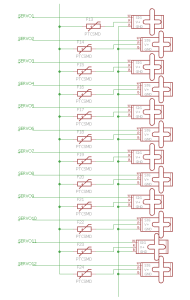
Once the interface definitions were developed, connecting the pins using EAGLE was simple. In order to keep the EAGLE schematic looking neat and legible, we used a second page for the servos. By changing the name of the wires, the wires can be connected across different pages. It is important when changing the name of the wires to put a note on the wire that is being named so that the pins from the ATmega1280 are clearly shown. Another issue we were having was that on the second page with the servos, a few of the VCC and GND wires looked like they were connected to the servo, but in reality, they were not actually connected. Once we were sure that all of the pins were connected properly, the layout was easily completed.
Alternative Arduinos
By Henry Ruff (Electronics and Controls Engineer)
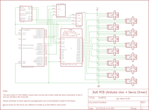
For the option of using an Arduino board aside from the Mega, there are some considerations. First of all, there will not be enough pins to accommodate all of the sensors and the 12 servos, so a servo driver would be needed for the servos. An early PCB design utilized the Adafruit 16-Channel 12-bit PWM/Servo Driver, as shown in the following image.
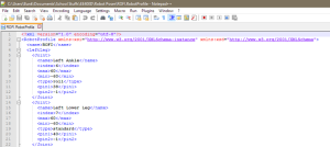
However, further complications were found when working with Robot Poser. The source code was never made available, so there was no room for modifications. The real problem was in the “Rofi.RobotProfile” file that Robot Poser uses, there is direct addressing of pins that can only be found on an Arduino Mega.
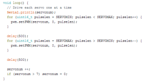
In the servo driver code, its method of addressing a particular servo is by using a variable, as shown in Figure 8. This conflicts with the method that Rofi.RobotProfile uses, and since Robot Poser itself cannot be modified, using anything but the Arduino Mega while also using Robot Poser is simply not possible. These complications were primary factors leading to us implementing the ATmega1280 chip directly onto the PCB instead of using a different Arduino.
Custom Eagle Parts
By Henry Ruff (Electronics and Controls Engineer)
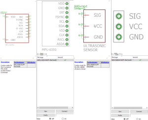
To simplify the PCB design and make it easier for future renditions of RoFi, we created custom EAGLE components for the Invensense MPU-6050 Accelerometer/Gyroscope and the SEN136B5B Ultrasonic Sensor. The former has a space laid out for it to be placed directly above the PCB, while the latter is ideal at the edge of the PCB as it can stick out due to its right-angle headers. These files were consolidated into a custom RoFi library that can be added to EAGLE, and is available below.


