Spring 2016 RoFi: Research Projects and Creative Exercise
Christopher Andelin (Project Manager)
Mario Ramirez (Systems Engineer)
Qui Du (Manufacturing Engineer)
Andrew Laqui (Electronics and Controls Engineer)
Henry Ruff (Electronics and Controls Engineer)
Table of Contents
Project Manager Research
Christopher Andelin (Project Manager)
Source Material
- Project Biped, Overview; http://www.projectbiped.com/prototypes/rofi
- Micro BiPed Introduction, Mission Objective and Mission Profile; http://arxterra.com/micro-biped-intoduction/
- Micro BiPed Requirements; http://arxterra.com/requirements/
- Micro BiPed Requirements Level 1 and 2, Cost, and Schedule; https://www.arxterra.com/final-documentation-microbiped/
- The Engineering Method; http://web.csulb.edu/~hill/ee400d/Lectures/Week%2002%20Engineering%20Method/b_Engineering%20Method.pdf
- Mission Profile and Project Objective; https://www.arxterra.com/fall-2015-microbiped-redefining-mission-objective/
- Mission Objective, Mission Profile, Level 1 and Level 2 Requirements, Cost, Schedule; https://www.arxterra.com/wp-content/uploads/2015/05/Spring-2015-%C2%B5BiPed-Perliminary-Design-Document.pdf
Mission Objective and Mission Profile
The Project Objective and Mission Profile is a statements of a problem to be solved. If along the way the customer changes their minds it is okay to let the customer know that the change is out of scope and there may be an increase in cost of schedule slip. The Mission Profile confirms that the Engineers design solves the customers’ problem through validation tests.
The Spring 2015 Mission Object biped project does not state a problem to be solved instead explains that the goal is to shrink the design to a micro biped. The Mission Profile comprises of validation tests that are specific and appear feasible due to the design of the micro biped.
Level 1 program/ project requirements
The requirements of Spring 2015 biped project done correctly
- requirements are quantitative, verifiable and realizable
- provided source material
- moves the design process forward
- located at the correct level (1- program/project)
- requirements are separated
Done incorrectly
- used the word must instead of shall
- no equations
Costs
- The predicted cost of Spring’s 2015 biped project was $395.15 and the actual total cost was $277.13 (source 4)
- Our Preliminary budget is $300.00
Scheduling
The Spring 2015 biped team spent a lot of time on planning, reviewing code, selecting a microcontroller, manufacturing, software and testing. It is advised to prepare for unforeseen circumstances (source 4).
Systems Engineer Research
Mario Ramirez (Systems Engineer)
Source Material
1.”Project Biped”, 1/31/2016 http://www.projectbiped.com/prototypes/rofi
2.”Fall 2015 microBiPed Summary”,BiPed, Page 1, 1/31/2016 https://www.arxterra.com/fall-2015-microbiped-summary/
3.” Fall 2015 MicroBiPed Verification and Validation Tests”, BiPed, Page 1, 2/1/2016 https://www.arxterra.com/wp-content/uploads/2015/12/Test-Plans-for-Verification-and-Validation.pdf
4.” Fall 2015 MicroBiPed Center of Mass”, BiPed, Page 1,2/1/2016 https://www.arxterra.com/fall-2015-microbiped-center-of-mass/
5.” Fall 2015 MicroBiPed Stress Analysis”, BiPed, Page1,2/1/2015 https://www.arxterra.com/fall-2015-microbiped-stress-analysis/
6.” Fall 2015 MicroBiPed Wiring Diagram”, BiPed, Page ,2/1/2016 https://www.arxterra.com/fall-2015-microbiped-wiring-diagram/
7.” Fall 2015 MicroBiPed Center of Mass”, BiPed, Page ,2/1/2016 https://www.arxterra.com/fall-2015-microbiped-center-of-mass/
- “Fall 2015 MicroBiPed Preliminary Project Plan”, Biped Page , 2/8/2016 https://www.arxterra.com/fall-2015-microbiped-preliminary-project-plan/#Requirements_Verification_Level_1_8211_Program_Requirements
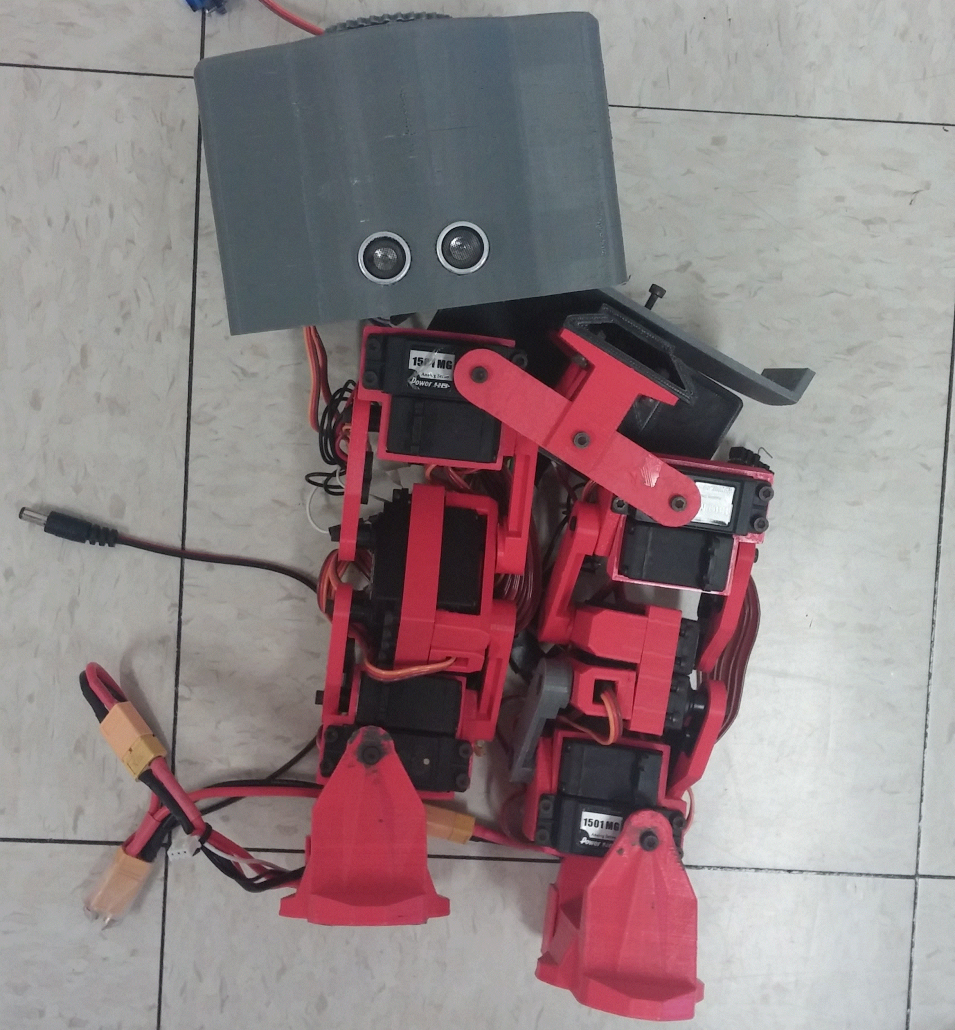
RoFi is a two legged BiPed robot designed by Jonathan Dowdall. RoFi should be able to walk on only two feet without falling over, avoid walls as well as other objects. RoFi should be able to do these operations by communicating with the Arxterra app.
As the system engineer of the RoFi project group I am in charge of assisting with level 2 requirements, the cable tree, box diagrams, intangibles, testing, and verification/validation. Reviewing Jonathan Dowdall’s website and the BiPed section on the Arxterra blog I have come up with a review of RoFi.
Level 1 requirements for RoFi consist of maintaining balance, be able to detect and adapt to incline or declines, avoid walls and objects using an ultrasonic sensor, and be able to communicate with the Arxterra app. Most of requirements posted by previous teams were for a microBiPed. Since we are working with an original size BiPed the level 1 dimension requirements do not apply to us and were omitted. All these requirements are qualitative in my perspective because they give exact detail on what RoFi must be able to do and also lead to a design and further level 2 requirements.
Level 2 requirements for RoFi specify what is going to be designed in order to achieve the level 1 requirements. For the level 1 requirement of avoiding walls to be met the level 2 requirement should state what sensor is being used and the reasoning behind it. Some previous groups state using a ultrasonic range sensor and other groups do not state the sensor at all in their requirements. For our level 2 requirements to lead to a proper design I think we need to state what sensor we will be using and why we chose that sensor. Another level 2 requirement obtained from the blogs will be the use of a gyroscope to sense the incline or decline of the surface. However, some research has lead me to believe that the gyroscope is not the most effective sensor. Testing an accelerometer and comparing it to a gyroscope might lead to possible solutions. Other level 2 requirements consist of: usage of Arduino Mega, Bluetooth used to communicate with Arxterra app, and grip pad on the soles of RoFI. These requirements meet a qualitative and quantitative criteria in order to push the design of the project forward.
Validation/verification go hand in hand with requirements because the validation form goes through the requirements and states if and how those requirements were met. I think previous teams did a good job with their validation form because I was clearly able to understand what requirements were easy to meet, which were more difficult, and which requirements were not able to be met.
Tests done for the BiPed robots consist of power distribution testing, servo torque testing, limb strain testing, and center of mass testing. The blogs from previous teams state clearly the experiment they did and the results achieved. However, not much detail in the process of how the experiment was always given. I think enough detail should be given so the next engineer could redo the experiment if needed. I also believe more testing on the ultrasonic sensor should be done. Previous teams have testing on the connections of the sensor, but I did not see testing on the range of the sensor or if any objects cannot be distinguished by the sensor.
Intangibles are an important task for the systems, missions and tests division of any project. I read some intangibles within tests of previous teams, but for clarity and future teams I believe a structured table would be beneficial so it is clear what teams in the future need to test for their design.
Electronics and Controls Engineer Research
Andrew Laqui (Electronics and Controls Engineer)
Source Material
https://www.arxterra.com/microsegbot-fall-15-final-document/
https://www.arxterra.com/spring-2016-velociraptor-roles-responsibilities/
- MicroSegbot Fall 15′ Final Document, Level 2 Requirements #7, February 2, 2016 https://www.arxterra.com/microsegbot-fall-15-final-document/
- MicroSegbot Fall 15′ Final Document, Bluetooth Trade-Off Study, February 2, 2016 http://arxterra.com/bluetooth-trade-off-study/
- MicroSegbot Fall 15′ Final Document, Microcontroller Trade-Off Study, February 2, 2016 http://arxterra.com/microcontroller-trade-off-study/
- Final Documentation MicroBiPed, Requirements level 1 and 2, Level 2 Requirements #1, February 10, 2016 http://arxterra.com/requirements/
- Final Documentation MicroBiPed, Requirements level 1 and 2, Level 2 Requirements #9, February 10, 2016 http://arxterra.com/requirements/
The level 2 requirement #7 from the MicroSegbot project from Fall 2015 stated that the robot must utilize a microcontroller that will support each component that is used in accomplishing the program requirements.
- This requirement was not quantitative, but it was verifiable and realizable. The nature of this requirement was that it could not be quantitative. This requirement was a direct response to the level 1 requirement that stated, “The MicroSegbot will use an android phone/laptop to navigate wirelessly by the customer.” This requirement was appropriately a level 2 requirement because it was a requirement that would directly cover a level 1 requirement. There were no links in the document for this requirement other than a link to the beginning of the design document. This requirement moved the design process forward because it determined how the robot was controlled. There were no equations in this requirement. The language was not in the form of a requirement; the author did not use the word “shall” nor the word “should”.
The Bluetooth Trade-Off Study from the MicroSegbot project from Fall 2015 considered the level 2 design requirement #3. The author stated that Bluetooth communication was required because the robot was to be controlled by an android phone.
- The trade-off study is quantitative because it speaks to the specific values for the specifications of two different Bluetooth devices. The study did not seem to contain any non-essential information. The study clearly expressed why the preferred device was chosen.
The Microcontroller Trade-Off Study from the MicroSegbot project from Fall 2015 considered the level 2 design requirement #7.
- The study was quantitative because it compared 3 different devices based on different numerical values. The study does not contain any non-essential material. It compares nine different specifications that are all relevant to deciding which microcontroller would be preferred.
The level 2 requirement #1 from the μBiPed project from spring 2015 stated that the robot will utilize an HC-SR04™ ultrasonic sensor. The reason for this sensor is that it is less susceptible to noise and cost.
- The requirement was not quantitative, but it was verifiable and realizable. The nature of this requirement is that it cannot be quantitative. It is located in the correct level because it clearly stated which level 1 requirement it was linked to. The requirement also contains a link that goes to the sensor study. This requirement moves the design process forward because the customer specifically wanted the robot to avoid obstacles, and this sensor will allow the robot to do that. No equations are used. The author should use the word ‘shall’ rather than ‘will’ in order to use the proper language for a requirement.
The level 2 requirement #9 from the μBiPed project from spring 2015 stated that a Bluetooth IC will be chosen to communicate with the Arxterra™ program. An IC must be used in order to minimize the μBiPed size and mass. The type of Bluetooth IC is HC-06.
- The requirement was not quantitative, but it was verifiable and realizable. The nature of this requirement is that it also cannot be quantitative. It is located on the correct level, and it clearly stated which level 1 requirement it was linked to. The requirement does not contain any links to any source material. It could use a link to the specs for the IC or a link to a trade-off study as to why that IC was chosen. This requirement moves the design process forward because the customer wanted the robot to be able to be controlled remotely using the Arxterra™ program. No equations were used. The author should use the word ‘shall’ rather than ‘will’ in order to use the proper language for a requirement.
Manufacturing Engineer Research
Qui Du (Manufacturing Engineer)
Objective:
As a Manufacturing Engineer, I will be responsible for the PCB layout and assembly. My job is using the Eagle CAD programing to design the PCB (printed circuit board), perform ERC (electrical rule check) and DRC (design rule check), and generate the CAM file and upload to PCB house for fabrication. Beside of this, I also will be responsible for 3D modeling to design all Rofi printed parts by using Solidworks.
Source Materials:
- Barajas, Alejandro (Fall 2014).”Biped Final Documentation.” Arxterra Blog Post https://www.arxterra.com/final-documentation/
- Geijtenbeek, Thomas. “Flexible Muscle-Based Locomotion for Bipedal Creatures.” YouTube. https://www.youtube.com/watch?v=pgaEE27nsQw
- Kiley, Steven. “SolidWorks Intro Tutorial.” YouTube. YouTube, n.d. Web. 11 Feb. 2016.
https://www.youtube.com/watch?v=TvBoZ6kH3Q8
- Balagtas, Michael (Fall 2015).”MicroBiPed PCB.” Arxterra Blog Post
https://www.arxterra.com/fall-2015-microbiped-pcb/
- Blum, Jeremy. “Tutorial 1 for Eagle: Schematic Design.” YouTube
https://www.youtube.com/watch?v=1AXwjZoyNno
REVIEW OF MATERIALS:
- This blog is well organize and useful. I really love the “Ideas and advice for future classes” section because the biped project is hard project that maybe not be done in semesters or even years; It is helpful if a previous semester student document all of the obstacles and suggestions for future semester student to review. From this blog, I learn that getting a prototype for a Rofi before getting parts 3D-printed is very important because prototypes allow the team to see any probable design conflicts that can be corrected before final 3D-prints. This technique could save a lot of money and time. The other great advice that I learn from this blog is try to make a physical layout of how I imagine the board to look. Because even the PCB layout was designed correctly and functionality; in some circumstance, It might not match with pins of components which needed to attached to PCB layout. This issue might take a team a lot of time to solve or even lead the team to redesign a PCB layout; therefore, it is important to make a physical layout of how we imagine the board to look.
- As a manufacturing engineering, my main job is to design 3D modeling of a Biped on Solidworks; It is useful for me to visualize the flexible Muscle-Based locomotion for Bipedal creatures. From above video, it shows a control 3D muscle actuation of a biped which helps me to realize that the different dimension of a biped will lead to different types of movement so that I can choose the dimension type of my biped.
This video also shows how to optimize for different target speeds (different dimension of a biped have different target speeds). For example, for a too wide Bipet, we will be faced with an issue of low speed; however, for this type of biped, we will take an advantage of avoiding the biped to fall sideway. In contrast with a too wide Biped, a too tall Biped could achieve a high target speed, but it has an issue with being easy to fall down to all direction. From this information, I realize that the outfit of a biped is very important consideration to design a good Biped which could match with requirement of balancing and achieve a target speed. In other words, in order to design a desirable target speed biped, I really need to design the right outfit for the Biped.
- To get ready to handle my jobs position, I do self-training my 3D modeling by watching above training video. This video is well organize, and easy to follow step by step. It helps me to be familiar with Solidworks and future designing of printed parts for the Rofi such as: foot, servo band, servo wrap, or knee frame.
- From above blog, the manufacturing engineer had a problem with a free version of EAGLE since it has a limit of 2in x 2 1⁄2in; therefore he/ she did not have the liberty of space to maneuver around the conflicted part. If I am in this situation, I suggest he/ she tries to use a license version of EAGLE from school or try to reorganize the wires and components to make them more space less.
- As important as 3D modeling, Eagle CAD is software that I use to build the PCB layout. To get handy with this tool, I also watched some of training tutorials online and followed the instructions to repeat rebuilding it. By following the tutorial, here is a final result.
Electronics and Controls Engineer Research
Henry Ruff (Electronics and Controls Engineer)
Source Material
Project Biped
Jonathan Dowdall
- ROFI – Project Biped, 2/3/2016, http://www.projectbiped.com/prototypes/rofi
- Progress Setbacks, 11/7/2011, http://www.projectbiped.com/updates/blog/progressandasetback
- ROTH post mortem, 1/11/2012, http://www.projectbiped.com/updates/blog/rothpostmortem
- ROFI parts list, 2/3/2016, https://docs.google.com/spreadsheets/d/1PdzezPRsNnxsz-CfU83IURZGI23ftaexhAVR2sCV_Vs/edit#gid=0
Arxterra
- Requirements, 2/8/2016, https://www.arxterra.com/requirements/
- Fall 2015 MicroBiped Motion Sensor, 12/7/2015, https://www.arxterra.com/fall-2015-microbiped-motion-sensor/
- Fall 2015 MicroBiped Distance Sensor, 11/2/2015, https://www.arxterra.com/fall-2015-microbiped-battery-update/
- Fall 2015 MicroBiped Microcontroller, 11/3/2015, https://www.arxterra.com/fall-2015-microbiped-microcontroller/
- Fall 2015 MicroBiped Servo, 10/23/2015, https://www.arxterra.com/fall-2015-microbiped-servo/
Review of Literature
Project Biped – This documentation on projects ROFI and ROTH provides insight on design complications and specifications necessary for the requirements of building a bipedal robot. These studies elaborated on level-2 design requirements, with each portion working towards furthering the overall design. For more detailed specifications, the ROFI parts list provides exact components used previously, and this is a useful reference point. The ROFI website itself is a more direct resource as compared to the Arxterra posts, as the latter is not specifically for ROFI itself.
Arxterra – The Arxterra blog posts presented insight on component options and testing performed by previous, comparable biped projects. Furthermore, they outlined requirements for biped projects that can similarly be applied to the ROFI robot.
Requirements – A compilation of understanding of the previous articles, as well as observations and personal commentary on necessary adjustments or changes to the project overall.
- Autonomous bipedal walking
- Balanced during each frame of walking movement
- Fast movement would keep balance, such as with human walking, but this is unfeasible for this project. Instead, slow movement would necessitate being able to have a center of gravity that is balanced during each frame of movement.
- High torque servos
- Microcontroller to handle servos
- Servos cannot be utilized constantly due to risk of overheating
- Servos should withstand weight of overall project
- Servo strength/torque can be determined by physics calculations or modeling experimentation
- If the overall weight can be reduced, then lighter servos can also potentially be used.
- Able to handle sloped surfaces as well as varying textured surfaces
- Gyroscope and accelerometer are viable for feedback that can be read and therefore controlled, to be able to make ROFI react in a way that will allow it to balance. Accelerometer is better able to handle inclines, as explained in the source material above.
- Grip exists on the soles of ROFI’s feet, allowing it to be able to walk on feasible surfaces. Its movement also should raise each foot a high enough distance while remaining flat, to be able to avoid complications that would occur if its feet moved very close to the ground.
- Pathfinding around obstacles
- Can utilize ultrasonic or infrared sensors to determine distance and appropriate response, such as stopping at a gap or turning at a wall.
- Needs a method of turning through bipedal motion
- Design can be modified or servos used in a way that creates rotational torque to turn the body while still keeping balance
- Obstacles include objects in the way as well as terrain differences
- Controlled by Arduino board, with interaction with a mobile phone app.
- As ROFI is autonomous, the main app interaction will be to turn it on or off.
- Stabilization if disturbed by an external force from any angle, at any point of ROFI, and at any strength.
- Accelerometer can be used to be read by ROFI, and then it will perform an appropriate equal force in the opposite direction to be able to balance itself.
- A force too strong will not allow for ROFI to respond quick enough to balance, so there must be a determined limit as to what ROFI can feasibly respond to.
- Balanced during each frame of walking movement
Creativity Exercise
Christopher Andelin (Project Manager)
Mario Ramirez (Systems Engineer)
Qui Du (Manufacturing Engineer)
Andrew Laqui (Electronics and Controls Engineer)
Henry Ruff (Electronics and Controls Engineer)
Problems
- The bolts screw directly into the plastic frame causing the bolts to come loose.
- Running time is 10 to 15 minutes.
- Cables are loose and exposed.
- Moving parts can cause harm.
Brainstorming Solutions
- Retrofit the broken frame by using SolidWorks 3D modeling.
- Screw hardware into rigid material instead of the plastic frame.
- Redesign current material by making it lighter ( less power consumption, help the battery last longer)
- Use lighter material for Rofi, for example: wood, aluminum, cardboard paper.
- Use shorter cables, reroute, and/or use enclosure
- Design a material that can be placed around RoFi’s legs in order to cover the moving parts and cables. Pants with pockets can hold various objects.
Lateral Thinking
Forced Relationship:
- Cheerios – Honey comb pattern for printed limbs. This will reduce weight since less material will be used. However, stress tests would need to be done in order to verify the new design could handle RoFi’s movement.
- Volleyball – Use as a protective layer to protect internal components and protect user.
- Baby – Rofi can act as a baby monitor. It will follow the baby around, and if the baby cries, Rofi will notify the parent via cell phone.
Different Point of View
- Rofi – “What kind of accessories can I have?”
- Reprogram RoFi to allow one leg remain bent when attached to a skateboard while the other leg kicks and pushes.
- RoFi can have an assortment of outfits to customize the appearance.
- Dress/Wig
- Army Uniform
- Customer – “How else can I use RoFi other than just for a toy?
- Program alarm clock to the phone. When the alarm goes off in the morning, RoFi will walk away, forcing the customer to catch up to RoFi and turn off the alarm.
Experiments
- Stress test for frame and hardware.
- Test the flexibility of the volleyball material
- Verify that changes do not impede movement
- Overall heat of the system needs to be tested to insure that the added material will not cause RoFi’s components to overheat.
Questions
- Is there a way to lower costs?
- Will shorter cables impede movement?
- How will the phone be attached?
- Can we remove any unnecessary parts?
- Should we color code the wires?
- Can we salvage PCB parts?
- Can we use a smaller Arduino?
- Can we upgrade the power supplies?
- Are there any maintenance that needs to be performed?
- Does RoFi need to be stored in a particular environment?