Spring 2016 3D SMD: Research Project
By: Bao Loc Doan (Project Manager)
Christine Vu (Systems Engineer)
Henry Nguyen (Electronics Engineer)
Nasser Alsharafi (Manufacturing)
Project Manager Research
Bao Loc Doan (Project Manager)
Mission Objective
When humans manually pick and place surface mount components onto a printed circuit board (PCB), there are problems with human accuracy and time efficiency. A pick and place surface mount device (SMD) is an automated device that can populate a printed circuit board (PCB) with surface mount components (resistors, capacitors, and IC chips) by referencing a Gerber file. The SMD pick and place machine will be able to pick the surface mount components up and place the components down at the correct location until the board is finished. The objective of this project is to create a pick and place SMD machine and the customer has expressed the desire to keep the overall budget of the project to be around $600.
Creativity
All creative ideas and brainstorming were done prior to establishing a firm base. You can read about our ideas given below in the link.
https://docs.google.com/presentation/d/1F_2NlVyMoYl47WXqDsclBF27teGJwjQjFWzvZX9yafo/edit?usp=sharing
Level 1 Requirements
To satisfy our gracious and generous customer, a list of requirements that our end product needs to meet were created. These requirements takes into account functionality, appearance, and price.
- The pick and place SMD machine shall pick up the component and place down the component with a 0.05 mm error (specification of Madell Corporation Model DP2006-2) .
- The pick and place SMD machine shall be able to complete at least one PCB.
- Arduino software for the pick and place SMD machine shall accept accurately at least one Gerber file per requirement of the course.
- The pick and place SMD machine shall operate automatically after pressing start once.
- The pick and place SMD machine shall be able to pick up from 4x 8mm reel feeders and an IC tray.
- Total cost of finished project must be under $600.
- Deadline to complete the pick and place SMD machine shall be before the end of Spring Semester 2016.
Work Breakdown Structure
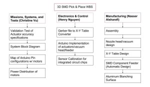
The goal is to produce a working prototype by the end of the school semester (approximately 15 weeks). In order to meet that goal, a WBS (Work Breakdown Structure) needed to be created in order to allow group members to focus on their own specific divisions. The following graph is the WBS that I and our system engineer, Christine Vu, developed.
Figure 1 – Work Breakdown Structure
Product Breakdown Structure
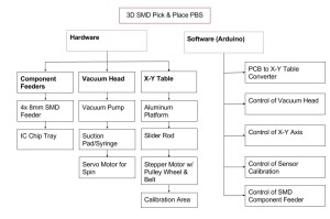
Now that we’ve developed what our WBS is, the next step that we took was developing a PBS (Product Breakdown Structure). The PBS will allows us to map out the key components of our design.
Figure 2 – Product Breakdown Structure
Budget
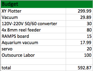
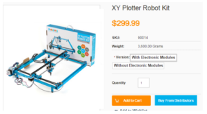
Our preliminary budget ended up being slightly under the budget given by our customer. The bulk of the price (~$300) will be from the XY plotter that will be purchased from Ebay. Outsource labor takes into account the costs that the machinist will charge for their services. This number is merely an estimation and the number was given to me by a connection that I have to a machinist that would be willing to work with us.
Figure 3 – Estimated Budget
Systems Engineer Research
Christine Vu (Systems Engineer)
As a systems engineer, one must consider the components that make up the project design to formulate requirements, functionality, and progress.
For the pick and place Surface Mount Device (SMD) machine, we had to include both the course’s requirements and requirements that will progress the design. In the requirements section, words like “shall”, “must”, and “will” are equivalent and are mandatory to move the design forward. Words like “may” are suggestions that are optional to the design. It is also important to note that the table to hold PCB and the X-Y Table is used simultaneously and are equivalent. During the requirement-forming process, Henry Nguyen (Electronics) and I went over subsystem requirements while Bao Loc Doan (Project Manager) and I went over system requirements.
Level 2 System Requirements
Level 1 Requirements (L1):
- Pick and place SMD machine shall pick up the component and place down the component with a 0.05 mm error.
Level 2 System Requirement (L2):
L2 -1 SMT component shall have a vibration displacement of less than 0.05 mm from its original spot during the entire operation. This requirement is so that the placement of the SMT components would prevent incrementing error.
1. The pick and place SMD machine shall be able to complete at least one PCB.
Level 2 System Requirement:
L2 – 2 Noise level of pick and place SMD machine during run-time shall be under 40 dB. This is a requirement so it would not disturb our customer.
- Software for pick and place 3D SMD machine must be able to translate maximum PCB size of a 4” x 3.2” Gerber file schematic.
Level 2 System Requirement:
L2 -3 Gerber file shall include at least one 0402 component. This is per requirement of great leader Hill.
- Pick and place SMD machine shall operate automatically after pressing start once.
Level 2 System Requirement:
L2 – 4 Pick and place SMD machine shall send zero error feedback.
- Pick and place SMD machine shall be able to pick up from 4x 8mm reel feeders and an IC tray.
Level 2 System Requirement:
L2 – 5 Pick and place SMD machine shall be clear of debris during operation, which would be pieces that are not part of the SMT components and are larger than the 402 metric component (0.4 mm x 0.2 mm, or 0.0157” x 0.0079”) and include wires. This requirement is so that when the PCB board is placed on a smooth surface, the application of solder paste will not be interfered.
- Cost must be under $600.
Level 2 System Requirement:
L2 – 6 Pick and place SMD machine budget sheet shall be under $600.
- Deadline to complete pick and place SMD machine’s final assembly shall be before the end of Spring Semester 2016.
Level 2 System Requirement:
L2 – 7 Pick and place SMD machine assembly schedule shall be submitted before February 11, 2016 at 11:59 PM.
Initial System Block Diagram
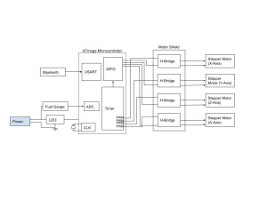
This block diagram was based on the Arxterra blog posts on RosCo from Fall 2015.It was discovered that the pick and place SMD machine can be operated using stepper motors as found through videos as shown on the MakeBlock X-Y Plotter. Another YouTube channel provided the entire run-through of the pick and place 3D SMD machine assembly, Scientist Razz. References of these videos are shown at the end of this blog post.
Figure 1. Initial System Block Diagram will control stepper motors.
System Interface Matrix
Pins on motor shield will be determined after further research on the benefits of buying a shield designing one.
| AVR | Arduino | Bluetooth |
| PD0 (RX) | Digital Pin 0 | TX |
| PD1 (TX) | Digital Pin 1 | RX |
| PD2 (INT0) | Digital Pin 2 | Motor Shield |
| PD3 (INT1) | Digital Pin 3 | H-Bridge |
| PD4 | Digital Pin 4 | H-Bridge |
| PD5 | Digital Pin 5 | H-Bridge |
| PD6 | Digital Pin 6 | H-Bridge |
| PD7 | Digital Pin 7 | 3D SMD |
| PB0 | Digital Pin 8 | X-Axis Stepper |
| PB1 | Digital Pin 9 | Y-Axis Stepper |
| PB2 | Digital Pin 10 | Z-Axis Stepper |
| PB3 | Digital Pin 11 | A-Axis Stepper |
| PB4 | Digital Pin 12 | |
| PB6 | Digital Pin 13 | |
| PC0 (ADC0) | Analog Pin 0 (Digital Pin 14) | |
| PC1 (ADC1) | Analog Pin 1 (Digital Pin 15) | |
| PC2 (ADC2) | Analog Pin 2 (Digital Pin 16) | |
| PC3 (ADC3) | Analog Pin 3 (Digital Pin 17) | |
| PC4 (ADC4) | Analog Pin 4 (Digital Pin 18) | |
| PC5 (ADC5) | Analog Pin 5 (Digital Pin 19) | |
| PC6 (ADC6) | RESET |
Figure 2. System Interface Matrix.
Validation Matrix:
| Validation Product | Activity | Objective | Method | Results |
|
Pick and place SMD Machine (Overall)
|
Customer will evaluate overall functionality and display of pick and place machine.
|
1.) Ensure that L2-1 and L2-2 are complied. 2.) Ensure that errors occurred during operation are picked up by machine per requirement L2-4. 3.) Ensure that machine is clean (clear of debris) per requirement L2-5. 3.) Evaluate overall budget costs per L2-6 and L2-24.
|
Test — Vibration displacement of SMT component must be measured using precision caliper with +/- 0.002 mm tolerance and presented to customer. | |
| Test — Measurement of noise level may be used by phone application. | ||||
| Analysis — To evaluate budget costs, documentation of purchased products and an excel sheet that includes all pick and place SMD machine components shall be submitted. | ||||
|
Gerber File
|
Customer will view specifications on Gerber file.
|
1.) Ensure L2-3, L2-20, and L2-21 are complied.
|
Analysis — Present Gerber file that would be used and include the smallest component 0402. | |
| Analysis — Create software to translate 4″ x 3.2″ Gerber schematic. | ||||
|
Stepper Motor Operation
|
Customer shall evaluate motor display and software. This is combined because software will control the stepper motors.
|
1.) Ensure that L2-19, L2-20, and L2-21 are complied.
|
Test — Stepper motor temperature may be measured on the outer surface. | |
| Test — Error must be recognized by the software. Errors may be orientation of integrated circuit chips. | ||||
|
3D Axis (X, Y, Z) Control
|
Customer will evaluate motion of motors.
|
1.) Ensure that L2-12, L2-13 are complied.
|
Test — Submit data of X- and Y-axes presenting a straight movement at an angle of 0 degrees with 2.5 degrees tolerance. | |
| Test — Verification of Z-axes must present a straight movement of 90 +/- 2.5 degrees using data | ||||
|
Nozzle
|
Customer will evaluate overall functionality of nozzle.
|
1.) Ensure that L2-14, L2-15, and L2-16 are complied.
|
Test — Rotation of nozzle shall be controlled to present the 180 degree rotation. | |
| Test — During vacuum system assembly, allow vacuum to be constantly on to hold the SMT component upwards and record time for 4 seconds. | ||||
| Belt Pulley | Customer will evaluate assembly of pulley. | 1.) Ensure that L2-18 is complied. | Test — Verification of belt width and pulley wheel width may be measured separately. | |
|
X-Y Table/Aluminum Surface
|
Customer will evaluate assembly of working surface area that is X-Y table/aluminum surface.
|
1.) Ensure that L2-8, L2-9, L2-10, L2-11, L2-21, L2-22, and L2-23 are complied.
|
Test — Measure table with an accurate, precise ruler to determine the dimensions of drilled holes and gap between clamp and PCB. | |
| Test — Table slanting can be checked using a leveler or the pythagorean theorem based on dimensions measured by an accurate, precise ruler. | ||||
| Wire Connections | Customer will evaluate quality of wire assembly. | 1.) Ensure that L2-17 is complied. | Test — Verify that quality of wire connections are not strained and have slack. |
Figure 3. Validation Matrix that covers Level 2 requirements. Deadline requirements were removed.
References:
MakeBlock X-Y Plotter:
http://www.makeblock.cc/xy-plotter-robot-kit/
Scientist Razz:
https://www.youtube.com/watch?v=1aL7_8LJ4E8
42BYG Stepper Motor Datasheet:
http://www.micropik.com/PDF/42byg[1].pdf
System Block Diagram & Systems Interface Matrix was based on RosCo’s Fall 2015 Design:
http://arxterra.com/rosco-updated-interface-definition-fall-2015/
Gerber File Processing:
https://www.ucamco.com/files/downloads/file/81/the_gerber_file_format_specification.pdf
Electronic Engineer Research
Henry Nguyen (Electronic Engineer)
As an electronics and control engineer, we must consider possible softwares and hardware that help move our 3D SMD design process forward. An electronic engineer is responsible for several sub divisions such as PCB Design, Sensors, Actuators, and Power, and MCU Subsystem and Control Firmware. Due to this project being the first iteration of its kind, a lot of R&D needed to be done. PCB Design will be put on hold until it is required in the design.
PCB Design:
- We may need to design a PCB if the motor shield that comes with the X-Y Plotter does not power 4 H-Bridge due to an arduino output current of 40mA/
- Working from the interface matrix and block diagram created by our systems engineer (Christine Vu), we are required to design our Printed Circuit Board with maximum dimensions of 4”x3.2”.
- Create an electrical schematic in Eagle Cad.
- Create a Fritzing Diagram.
- Design and test circuit from our breadboard.
Sensors, Actuators, and Power:
- Stepper motor will rotate 180 degrees in order to pick up our components and orientate them on our PCB.
- Stepper motor are required for our vacuum head to move freely on our XY plotter.
- Determine power distribution of pick and place SMD machine.
MCU Subsystem and Control Firmware
- Write software that will control the vacuum head on our XY Plotter.
- Vacuum head on the A axis must be able to move freely within our X-Y working area of 10”x12” +/- 2” tolerance.
- The actuator will also need another servo that can rotate the nozzle 180°in order to pick up components.
- Translate commands into control signals.
- Modify Brian Dorey’s software for Pick and Place in C# and use Visual Studio to write the application using a smoothstepper ethernet board and Mach3.
- Based on Brian Dorey’s pick and place SMD, we will be legally using his software programs for our pick and place precision software.
- Find Gerber to Eagle translation
- Arduino may be used to control the feeder assembly
Subsystem Requirements
Level 1 Requirements (L1)
- Pick and Place SMD machine shall pick up the component and place down the component with a 0.05 mm error.
Level 2 Subsystem Requirements (L2 Sub):
Aluminum Table:
L2 – 8 Aluminum table will be 12.2047”x15.3543”(310mmx390mm) +/- 0.1” with small drilled holes in order to attach our clamping system.
L2 – 9 Table to hold PCB must be made of smooth aluminum with a clamping system which will be that holds the PCB with a gap of less than 0.5 mm.
L2 – 10 Table to hold PCB must be leveled at 0 +/- 2.5° with respect to the floor.
L2 – 11 Table to hold PCB shall be elevated to a minimum of 1” +/- 0.5” for solder paste heating.
Motor Movement:
L2 – 12 Motors moving in X-Y axes must be in a straight line at 0 +/- 2.5° with respect to the floor. The 2.5°tolerance is an estimate of human error. The physics of human error was only roughly studied due to the scope of this course.
L2 – 13 Motors moving in the Z-axis shall be moving in a straight line at 90 +/- 2.5° with respect to the floor.
L2 – 14 Motor that rotates the nozzle will be able to rotate 180° +/- 1°tolerance.
L2 – 15 At least one vacuum nozzle/head must be smaller than 0.4 mm x 0.2 mm (0.0157” x 0.0079”) by at least 0.1 mm +/- 0.05 mm. This size comes from the size of the smallest component, 0402 metric.
Vacuum System:
L2 – 16 Suction pressure of vacuum nozzle/head must be able to pick up integrated circuit components for at least 4 seconds.
L2 – 17 Wire connection configurations shall have a minimum bend radius of 11 times its diameter. This requirement is to relieve wire stress at rest and during operation.
L2 – 18 Width of belt to attach on pulley shall be less than 0.5 mm. This would help refrain the belt from slipping.
- Pick and place SMD machine shall be able to have a run-time of at least 4 hours.
Level 2 Subsystem Requirement:
L2 – 19 Temperature of stepper motor shall be under 131° +/- 1°Fahrenheit. This requirement is based on the 42BYG stepper motor that was used for the MakeBlock X-Y Plotter.
- Software for pick and place 3D SMD machine must be able to translate maximum PCB size of a 4” x 3.2” Gerber file schematic.
Level 2 Subsystem Requirement:
L2 – 20 Software shall translate with zero error.
- Pick and place SMD machine shall operate automatically after pressing start once.
Level 2 Subsystem Requirement:
L2 – 21 Software shall be able to recognize and self-correct all mistakes.
- Pick and Place SMD machine shall have a maximum of 4x 8mm reel feeders and an IC tray.
Level 2 Subsystem Requirements:
L2 – 22 X-Y Table must be large enough to hold the standard free Eagle PCB dimensions (4” x 3.2”), with at least 5” around the PCB perimeter. The length of 5 inches is a safe measurement so that the PCB does not slip off during pick up.
L2 – 23 Size of working area shall be within 10”x12” with +/- 2” tolerance. This requirement is based on the X-Y Plotter from MakeBlock that we may be purchasing.
- Cost must be under $600.
Level 2 Subsystem Requirement:
L2 – 24 Components of the pick and place SMD machine shall list prices rounded to the nearest $1.
- Deadline to complete the pick and place SMD machine final assembly shall be before the end of Spring Semester 2016.
Level 2 Subsystem Requirement:
L2 – 25 X-Y Plotter, pick and place SMD surface, and vacuum system (nozzle and vacuum pump) shall arrive before March 25, 2016.
Plan
I watched several videos on Arduino and understand the general idea about coding in C; however, I am unsure if the application of the Arduino will only be used for our reel dispenser or also be used for our precision software for our 3D SMD project. Until we get our XY Plotter, stepper motors, and design, I will not be able to write any software until we know exactly what goes where. I also understand that Ryland Watts and Nick Lombardo are great sources to learn Arduino and C. When the time comes and my Electronics and Control position is necessary for working with Arduino, I will be sure to contact Ryland, Nick, and other knowledgeable sources. A lot of research was done on the specifications of X-Y plotter and and possible design ideas in order to proceed with our project.
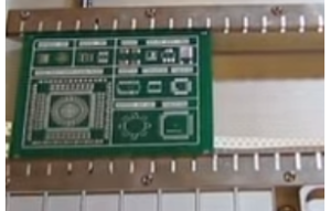
Figure 1 – Clamping System
Figure 2 – XY Plotter Robot Kit
References:
Brian Dorey’s SMD Project
http://www.briandorey.com/category/DIY-Pick-and-Place
Manufacturing
Nasser Alsharafi (Manufacturing)
Vacuum System
The vacuum pump works as follows. Essentially the air compressor or vacuum pump is connected to a one-way check valve. The one way check valve is a standard mechanical device that cost around 12$. The one way check valve is connected to an electric solenoid. The solenoid is controlled via a microcontroller programmed for specific timing intervals. The size of the solenoid hose connection should be ¼”.
The solenoid then connects to the pick up needle that is specified below. The needle needs to be small enough to pick up the smallest SMD part that it can. The tank is not needed however can be useful if it is disconnected or inactive for a period of time.
Vacuum Pump
The vacuum system is currently being researched and optimized. One thought is an electric air compressor, and the other is a 1200CC aquarium pump. The one way check valve, solenoid, computer-programmed microcontroller, are already specified but can be changed as necessary later if the project is altered in the future. The nozzle is being researched. So far specification for a 0.41 by 0.19 nozzle have been found and priced at 30$. The aluminum surface can be custom ordered to any size necessary.
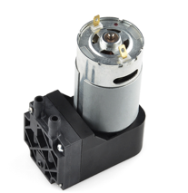
Figure 1 – Sparkfun Vacuum Pump
This is the Sparkfun Vacuum pump 12V. It cost around $15. It can work under 32° -120° F(0° -50°C). Most people who have used this device praised it for its quality. Most of the projects we researched online used this Vacuum pump for their pick and place projects. The only problem with is device that it might be noisy but since its relatively cheap we can try build a box that can reduce the noise. Also one of the methods that users reduced the noise for this pump is by running at lower voltage for example 8.5 volts, which was still able to lift a whole Bluetooth module. The barb connector is ¼” and should connect to another barb of same dimension.
An objective is that we want to keep the cost as low as we can. Perhaps, we would consider the electrical pumps as first, but if we want to make it cheaper possibly we could take the aquarium air pumps as an option. Aquarium Air pumps need to have the ability to make the tube pressured enough to pick the chips and place them at the board. As an example of an Aquarium Air pump we would consider Aqua Culture with 20 to 60 gallons, and its price is 7.61$. It has the ability to pump 1200 CC per minute. On the other hand, we have the electrical pumps that will be around 59$. Many reviews on the Aquarium Air state it has substituted the expensive electrical pumps very well.
Figure 2 – Aquarium Air Pump
Nozzle Head
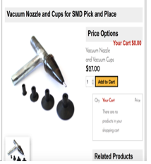
After that we researched the nozzle head. We found multiple ways that people implemented the nozzle head. Our requirements list that our nozzle must be smaller than the smallest 0402 component, which is 0.4 mm x 0.2 mm. we found many nozzles that can work for our project and the following is an example.
Figure 3 – Vacuum Nozzle
References:
Sparkfun Vacuum Pump:
https://www.sparkfun.com/products/10398
Nozzle Head:
http://www.aliexpress.com/store/product/SMT-MV-0402-NOZZLE/1457082_2050995547.html
Aquarium Air Pump:
http://www.walmart.com/ip/10532634?wmlspartner=wlpa&adid=22222222227001219214&wl0=&wl1=g&wl2=c&wl3=40341924752&wl4=&wl5=pla&wl6=56968315625&veh=sem

