Spring 2016 3D SMD: Makeblock XY Plotter
By Bao Loc Doan (Project Manager)
Table of Contents
MakeBlock XY Plotter
One of the main components on our PBS is the MakeBlock XY plotter. The XY plotter robot is originally a device that utilizes a pen or any other writing utensil to draw an image. Our design will involve the modification of the MakeBlock XY plotter in order to successfully become a pick and place SMD machine.
Software
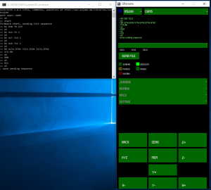
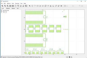
The XY plotter is equipped with two stepper motors that control the X and Y movements. These stepper motors will respond accordingly to locations set by the user through software. The files that the XY plotter reads are G-code (.CNC) files. After sending a .CNC file to the GCodeParser software, the XY plotter will begin reading coordinates and draw. This means a Gerber file to G-code file converter is crucial to our design.The two gerber files that needs to be converted to G-code are the solder mask top and silk top layers. These two layers will generate where each component needs to be soldered as well as a location name that can be referenced from a BOM (Build of Materials). I have researched into this and found a piece of software called FlatCam that could do this conversion.
Figure 1 – GCodeParser Software
Figure 2 – FlatCam Software
Assembly
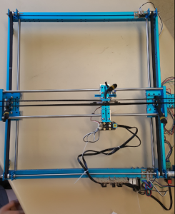
One of the issues that I came across while testing and assembling the XY plotter is that the instruction manual and firmware that came with the kit were outdated. Originally, the kit ships with an Arduino Leonardo but the newer model now ships with an Arduino Uno (Me Orion). This caused some error with the given firmware but after updating it with the proper firmware (from https://github.com/Makeblock-official) our system was up and running albeit with some errors. The limit switches on the XY plotter were not reading properly so the machine will continue moving even when the arm can no longer move. The movement of the XY plotter were also mirrored on both axis. If we wanted the plotter to move up, the plotter would instead move down. If we wanted the plotter to move left, the plotter would instead move right. The solution I found was that the connections given by Makeblock were wrong. After playing with the XY plotter for a while, I managed to get the connections so that the limit switches were reading properly and the movements were no longer mirrored.
Figure 3 – MakeBlock XY Plotter
Modifications
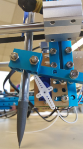
There are several modifications to this device that we have in mind. The accuracy of this device has a maximum error of 0.1 mm so we are thinking of implementing 5:1 geared stepper motors to control the X and Y axis. Trade-off studies for stepper motors will be conducted and presented in future blogs. We also have plans to modify the existing pen/marker system and implement a vacuum system with a nozzle in order to pick up and place down SMT components. Fortunately, the fittings on the XY plotter can already hold a pen so one of our ideas is to use a BIC pen casing and fasten on a luer syringe needle that has an opening diameter small enough to hold a 0402 component to the end. As it is right now, there is a micro servo that pushes the pen upwards and outwards when there is no need for it to have contact with the surface and after arriving at the intended location(s), the micro servo will release the pen back down. A trade-off study will need to be made to see whether or not this servo design will need modification.
Figure 4 – Micro Servo and Pencil Mechanism
The working area for the XY plotter is 310mm × 390mm (roughly 12.2″ x 15.4″) so there will be room for a 4″ x 3.2″ PCB, 4x 8mm reel feeders, and IC tray we are planning on implementing. Unfortunately, the XY plotter does not come with it’s own surface, meaning that the XY plotter will use whatever surface that it is placed on. In order to have a reliable flat surface that could heat up solder for future semesters to build on, there are plans to implement a blanchard grinding aluminum surface to the device.


