Spring 2016 3D SMD: Preliminary Project Plan
by Bao Loc Doan (Project Manager)
Christine Vu (Systems Engineer)
Henry Nguyen (Electronics Engineer)
Nasser Alsharafi (Manufacturing)
Table of Contents
Work Breakdown Structure
By Bao Loc Doan (Project Manager) and Christine Vu (Systems Engineer)
Our Work Breakdown Structure (WBS) was modeled after the Robot Project WBS. Each division will have tasks delegated to them and will be their primary responsibility to complete. As mentioned in 05 Preliminary Project Plan PDF, the WBS will be a “… hierarchical tree structure where each node (group) is the responsibility of only one engineer.” A completion of the WBS will indicate a successful project. The chart below will be the pick and place SMD machine WBS.

Figure 1. Work Breakdown Structure
Source Material
[1] G.Hill (2016, Feb). 05 Preliminary Project Plan [Online]. Available: 05 Preliminary Project Plan PDF
Project Schedule
A project schedule will lay out the deadlines that each engineer needs to conform to when assigned to their tasks. The schedule will allow the engineer to understand how much time they have left as well as the progression needed to complete the project. When deadlines are not met, there will be a chart illustrating the remaining cumulative work as well as baseline cumulative work.
Top Level Schedule
By Bao Loc Doan (Project Manager) and Christine Vu (Systems Engineer)
The top level schedule tasks were derived from our WBS. Each module in the WBS were taken into account. While working with the systems engineer, we developed a schedule that will divide all tasks in a progression that we believe will lead to project completion. Each required task will have a time estimate, and failure to meet the time estimated will result in the delay of every task assigned after. The chart below is the pick and place SMD top level schedule.
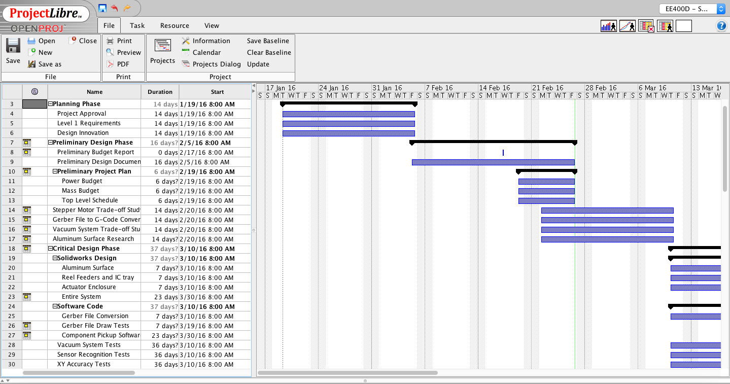

Figure 2. Top Level Schedule
System/Subsystem Level Tasks
By Bao Loc Doan (Project Manager), Henry Nguyen (Electronics Engineer), Christine Vu (Systems Engineer), and Nasser Alsharafi (Manufacturing)
Reference top level schedule for system/subsystem level tasks.
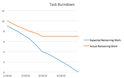
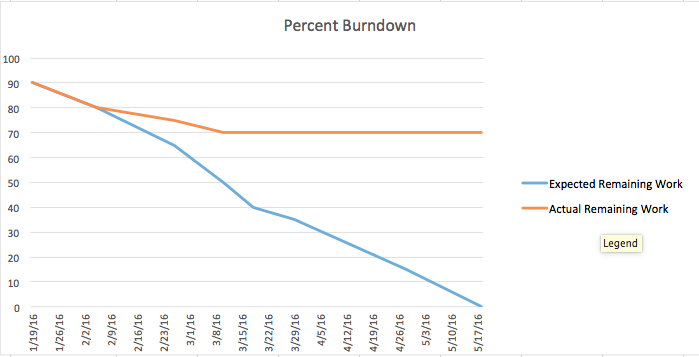
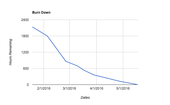
Burn Down and Project Percent Completion
by Bao Loc Doan (Project Manager)
A burn down graph is a visual representation of the expected progression and remaining progression. The top level schedule was created in ProjectLibre, so we had to use Excel to create a burn down graph. The task burn down and the percent burn down will be shown below.
Figure 3. Burn Down Graphs
System Resource Reports
By Christine Vu (Systems Engineer)
| Vacuum System Components | Preliminary Mass (g) | Uncertainty (%) | Margin (±g) | Expected Mass (g) | Actual Mass (g) |
| Stepper Motor (A-Axis) | 290.00 | 5% | 14.5 | 304.50 | |
| Stepper Motor (Z-Axis) | 290.00 | 5% | 14.5 | 304.50 | |
| Solenoid Valve | 99.79 | 5% | 4.99 | 104.78 | |
| Makeblock Stepper Driver (2 ct.) | 40.00 | 5% | 2 | 42.00 | |
| Vacuum Syringe | 68.00 | 5% | 3.4 | 71.40 | |
| Vacuum Tubing (25-ft.) | 68.00 | 5% | 3.4 | 71.40 | |
| Project Allocation | Trade-Off Study will be obtained | ||||
| Total Expected Mass | 898.58 | ||||
| Total Margin | 42.7895 | ||||
| Total Actual Mass | |||||
| Contingency | |||||
Table 1. Mass Report
Summary
The pick and place SMD machine will not need a power resource report because we are not limited in power. A waiver request will be submitted for approval.
The mass resource report is on the vacuum system to determine the mass. The stepper motor expected weight have been obtained from the Makeblock specifications on their X-Y Plotter Robot Kit (Shenzhen Maker Works Technology Co., Ltd., 2013).
The Makeblock Stepper Motor Driver is a component used to control the stepper motor with the ArduinoUno. It contains a stepper driver chip, 4 wire bi-polar stepper motors, a potentiometer, DIP switch, and a heat sink.
Because the components have not been purchased, project allocation, actual mass, and contingency will be obtained after trade-off studies have been conducted.
Source Material:
Shenzhen Maker Works Technology Co., Ltd. (2013). Me Stepper Motor Driver. Retrieved from:http://www.makeblock.cc/me-stepper-motor-driver/
Project Cost Estimate
By Bao Loc Doan (Project Manager) and Christine Vu (Systems Engineer)
| Resource | Unit Price ($) | Quantity | Shipping Cost ($) | Preliminary Cost ($) | Uncertainty (%) | Margin (±$) | Expected Cost ($) | Actual Cost ($) |
| MakeBlock XY Plotter Robot Kit | $267.66 | 1 | $0.00 | $267.66 | 8.00% | $21.41 | $289.07 | $267.66 |
| Tetra Aquarium Pump | $17.59 | 1 | $0.00 | $17.59 | 8.00% | $1.41 | $19.00 | |
| 8 mm Reel Feeders (Holds 4) | $32.00 | 1 | $0.00 | $32.00 | 8.00% | $2.56 | $34.56 | |
| Micro Servo | $7.00 | 4 | $0.00 | $28.00 | 8.00% | $2.24 | $30.24 | |
| 12V Solenoid Valve | $10.00 | 1 | $0.00 | $10.00 | 8.00% | $0.80 | $10.80 | |
| Aluminum Surface & Machinist Labor | $60.00 | 1 | $0.00 | $60.00 | 8.00% | $4.80 | $64.80 | |
| 42BYG Geared Stepper Motor | $60.00 | 2 | $0.00 | $120.00 | 8.00% | $9.60 | $129.60 | |
| Vacuum Tubing (25-ft) | $5.00 | 1 | $0.00 | $5.00 | 8.00% | $0.40 | $5.40 | |
| MakeBlock Stepper Driver | $18.00 | 1 | $0.00 | $18.00 | 8.00% | $1.44 | $19.44 | |
| Sensor Calibration | $50.00 | 1 | $0.00 | $50.00 | 8.00% | $4.00 | $54.00 | |
| Connectors | $2.00 | 2 | $0.00 | $4.00 | 8.00% | $0.32 | $4.32 | |
| $0.00 | $0.00 | 8.00% | $0.00 | $0.00 | ||||
| Project Allocation | $650.00 | |||||||
| Total Expected Cost | $612.25 | |||||||
| Total Margin | $48.98 | |||||||
| Total Actual Cost | $267.66 | |||||||
| Contingency | $86.73 | |||||||
Table 2. Cost Report
Summary
The cost report supports all parts needed so far to construct the pick and place SMD machine for Spring 2016.
The Makeblock XY Plotter is an XY plotter that can be easily modified to our needs. This specific XY plotter has a working area of 12” x 15” so it can easily fit our PCB fabrication requirements (4” x 3.2” as per free Eagle CAD board working area) and additional reel feeders. The Makeblock XY plotter ships all the parts as a kit and would be much more efficient to build since we would no longer need to design the entire XY plotter. The accuracy of this XY plotter needs to be increased by a factor of 2 (as requested by the customer) and a simple solution is to implement a geared stepper motor.
The Makeblock Gearbox Stepper Motor will be implemented into our pick and place SMD machine so our precision error meets customer standards of 0.002”.
The aquarium pump, solenoid valve, tubing, syringe, and connectors shall be used for the vacuum system in the pick and place SMD machine. The aquarium pump is easily modified to become a vacuum and the solenoid valve with brass fittings will control when the vacuum suctions in order to pick and up and place down the components as intended. The tubing, syringe, and connectors will connect each individual component to make the vacuum system.
All of our surface mount resistors and capacitors shall be placed in the 4x 8 mm reel feeders so they can be populated onto the PCB. After Spring 2016, 16x 8 mm reel feeders will be implemented into the pick and place SMD machine.
The aluminum surface will be the working area of the entire pick and place SMD machine. The machinist labor is included into the price. The Makeblock XY plotter will need to securely fit into the aluminum surface and there will also be an aluminum clamping system that needs to be drilled into the aluminum surface.
The Makeblock stepper motor driver will be used in conjunction with the Makeblock stepper motor to control our vacuum nozzle. In order for the vacuum to be able to pick up components, the ability to move in the Z-axis is required. We have plans to implement one Makeblock stepper motor on the z-axis and will need the circuitry required.