Spring 2016 Velociraptor: Hardware &Simulation
By: Mingyu Seo (Manufacturing &Design)
Introduction:
The purpose of this blog is to show the feasibility of the design we’re going to incorporate in to our robot. Using Solidworks, we’ll be able to validate center of mass of the robot when we’re performing static walking. Also by using the simulation on Solidworks, it’ll show the basic motion of the robot walking. Following hardware design will explain the problems and solutions we’ve made to find the most suitable design of Velociraptor.
Requirements:
Project Level 1:
- Requirement 1 states the Velociraptor shall resemble a Tyrannosaurus class of dinosaurs as given in the objective.
- Requirement 2 states the word “biped” is defined as having two feet; therefore, the Velociraptor shall use two legs to move.
- Requirement 4 states the Velociraptor shall be able to statically walk on all surfaces of the course
- Requirement 5 states the Velociraptor shall be able to dynamically walk on flat surfaces of the course.
Project Level 2:
- Requirement 4 states to resemble a Tyrannosaurus class of dinosaurs, the chassis of the Velociraptor shall be cut out in hollow body parts to assemble a frame-like body structure in a material that is cost effective
- Requirement 6 states to maintain balance while performing static walking, a head and tail shall be implemented to the chassis of the Velociraptor
Overall, the design of the robot must resemble a Tyrannosaurus class dinosaur, that walks on two legs, and by incorporating the head and tail will help keeping the robot balanced when it’s performing static & dynamic walk by shifting the center of mass using the weight of the head and tail. New designs were incorporated in to our new design to accommodate mass, price, and power budget.
Hardware Design:
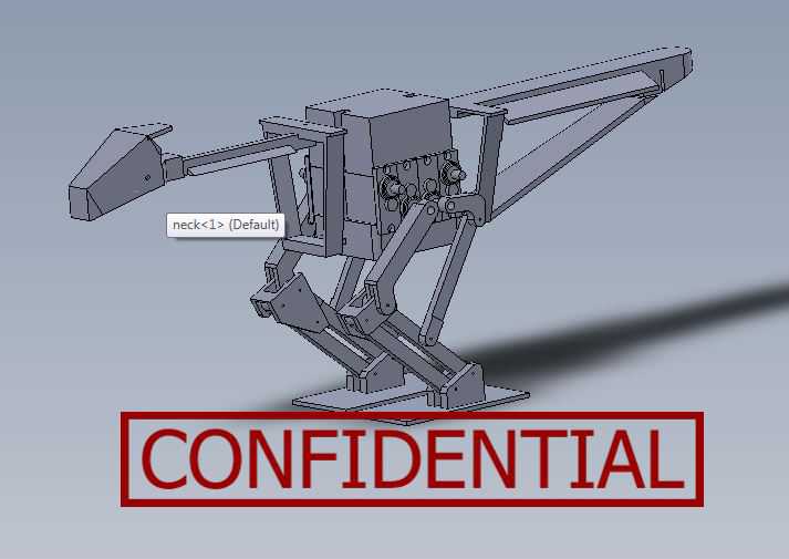
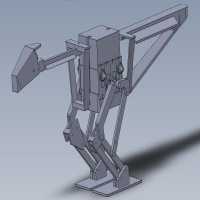
Figure 1. Final Design of Velociraptor (excluding sensors)

Figure 2. Exploited View of Velociraptor
First Design:

Figure 3. First design of the joint
Figure 3. shows the first design of the joint which incorporates the 3rd joint that was missing from the previous generation. The new design also incorporates a new design of the ankle where it’s connected with 2 parts rather than 1 that holds the leg and the foot, which helps the foot to stay parallel to the surface at all times.
Problem: when assembling the first design, we had few design problems
- The 3D printed parts were not sturdy
- Not strong enough to hold up the weight of the body
- putting too much pressure on the base of the foot started bending parts.
Second Design:
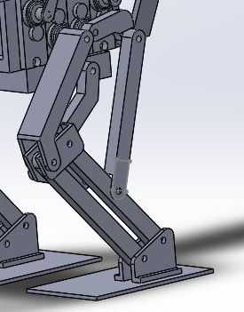
Figure 4. 2nd Design of the joint
Figure 4. incorporates the fixed design of our first design. We made all our parts minimum 0.3 cm thickness to prevent our parts from bending. The front joint that connects from front servo to the knee has thickness of 1.2 cm to have a more stable stance, and make sure it’s sturdy enough to hold the weight of the robot.
Problem:
- By increasing the thickness of the joints also increased the angle the head and tail must turn in order to shift the center of mass when performing static walk.
- When designing the 3D model, the design did not compensate the extra length added due to servo caps.
- The thickness of the foot was still too thin.
Final Design:
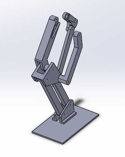
Figure 5. Final Design of the joint
Figure 5. shows the finalized design of the leg of Velociraptor.
Final Features:
- Shifted the front top joint (connecting from front servo to the knee) to the out in order help the robot to find center of mass by moving the head and tail less.
- Also have incorporated the placement for the servo caps to bring it closer to the center.
- All parts have minimum 0.3 cm to have a stable stance when it’s performing static walking.
- Extra length toward the back and outer side of the foot to have a more stable and balanced walking.
PCB placement:
First when we were designing the robot, we have decided to place all the sensors and the pcb underneath the servos. After finishing our PCB layout, we have found the size of the board too big to be placed under and due to the size of the voltage regulator it was not applicable to fit all the components under the robot. In order to solve this problem, we have decided to create a clear casing on top of the robot and place all our components in.
Design Features:
- Bottom of the case have been cut out in order to bring the wires underneath and hide it.
- hole has been placed on the front side of the casing to place the ultrasonic sensor.
- casing will be made with a clear PLA filament to show the components inside.
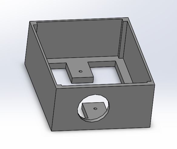
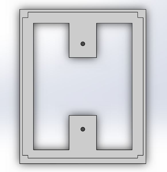 Figure 1. Design of the casing to hold up the PCB and also the top view of the casing
Simulation:
The simulation below shows the motion of the Velociraptor when it’s performing static walking.
In order to balance on one foot, we need to move the center of mass above the supporting leg by moving the head and tail toward the supporting leg for counter weight.

Conclusion:
This simulation shows the given dimension of the 3D model shows the feasibility of the design of the Velociraptor, and confirms the level 1 requirement 4, which states the Velociraptor being able to statically walk across the full course. The design that we have incorporated have been tested and resulted as successful when we’ve performed static walking. Biggest issue was trying to keep all wires and components hidden but due to the size of the PCB and the size of the voltage regulator heatsink we have decided to mount it on the top of the robot. The Head, Tail, and bottom plate for the robot was made with Aluminum, but the legs, top plate, and the PCB casing will be printed using PLA filament.