Spring 2016 Velociraptor: PCB layout
By: Mingyu Seo (Manufacturing & Design)
PCB Design:
For our design, we’ve started off by planning where our PCB is going to be mounted. Rather than placing it on top or inside the body frame, we’ve come up with mounting the PCB underneath the body to cover wires connecting all the components together. So, we have decided to mount the Arduino Micro as well as the accelerometer in order to minimize the number of wires connecting to the PCB. We decided to wire the Bluetooth toward the tail and the accelerometer on top to make sure it’ll be able to detect obstacles ahead.
Problems:
- The voltage regulator may cause too much heat.
- Minimum space to place all components
- Sensors mounted directly to the board must either be mounted so that they hang off the edge of the PCB, or the packages must be edited to include the physical shape of the device to avoid overlap of components.
Solutions:
- we will be using thru-hole heatsink method rather than PCB copper heatsink. Also by placing the voltage regulator to the corner, we will be using TO-220 Heatsink.
- Due to very little space provided for PCB layout, we will have to make sure to place the power supply as far away from the Bluetooth, accelerometer, and ultrasonic sensors as possible.
- we have a 5.12cm x 4.8 cm PCB layout, which must incorporate Arduino Micro, Accelerometer, Bluetooth, ultrasonic sensor, 8 Servos. By placing all the sensors on one side, we will be able to mount the accelerometer off the edge of the PCB, and connect Bluetooth and ultrasonic sensor with a wire.
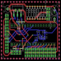
PCB Layout:
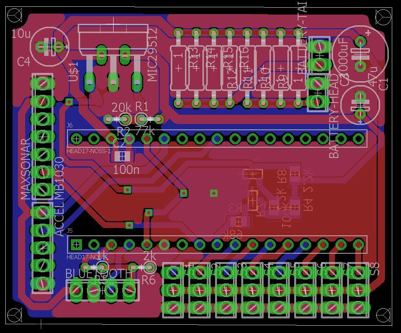
Finalized PCB layout
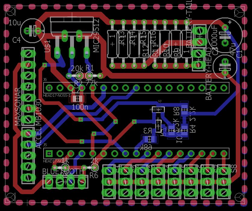
Finalized PCB layout Wiring