Spring 2017 BiPed – PCB Schematic
By: Abraham Falcon (Electronics and Control)
Approved by: Alexander Clavel (Project Manager)
Table of Contents
Introduction:
Electronics and Control engineer is to create a custom PCB and to layout the components to be used. The PCB components are a PCA9685 PWM expander, pin headers for the LEDs and a pin header for the color sensor.
Eagle Cad Schematic:
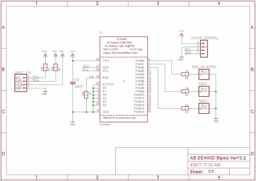
The Biped PCB schematic below shows what the main components are to be use with the 3Dot board, which is the color sensor and a LED counter.
This PCB schematic is the third version and to be used on the Biped mainly for the game. Previous PCB schematics had two extra servos from the main design of the biped. As we moved forward with the design of the Biped, the customer stated that the power was the be supplied without an external battery. Power should soley be provided by the 3Dot board battery. The servos were eliminated to reduce the power consumption and therefore the PCB schematic above is the final version to be used with the 3Dot Board.
The PCB needs to communicate with the 3Dot board and the PCA9685 PWM expander will handle this. The PCA9685 PWM expander handles multiple PWM pins as the 3Dot board does not provide. Connecting multiple devices to the PCA9685 PWM expander will communicate to the 3Dot board through the I2C bus.
There will be two LEDs for the Biped to represent the eyes that are colored red and signify that the robot is indeed on. The other LED which is green is to represent a counter for collecting colored dots from the “end of semester” Pacman Game. All the LEDs connect with a 1k Ω to PWM expander, which these resistors are to limit the amount of current going through the PWM expander for protection. The LEDs are not physically connected to PCB board therefore it will use pin headers so the LEDs can freely be placed anywhere around the Biped.
For the Biped to sense the color dots from the game it will be using a Adafruit RGB Color Sensor and this sensor will also not be physically connected. The colored dots are placed on the floor therefore the color sensor must be placed on the foot to sense the color dots. The pin headers have the connection needed to connect to the 3Dot board and be powered by it. The pin headers connect to the I2C bus from the 3Dot board, which are SDA and SCL. Also from the 3dot board the power and ground can be connected to the sensor provide from 3Dot board connection. The pin headers are placed so that the color sensor can freely be placed anywhere on the biped and for this design we chose it to be on the foot.
The other components on the PCB schematic were provide from the product website, where they also provided Eagle Cad files. All the components are surface-mount devices. These components were left alone as the product works with it.
Conclusion:
The completed PCB schematic is simple but pushed our design to have less power consumption and to participate in the “end of semester” Pacman Game. The completed PCB Schematic is sent to the manufacturing engineer to layout the PCB and to be completely assembled.

