Spring 2017 BiPed – Servo Turning Test
By: Jacob Cheney (Systems)
Approved By: Alexander Clavel (Project Manager)
Introduction
Based on mission objectives, where the BiPed has to maneuver through a maze in order to evade the Velociraptor, it is imperative that the BiPed is able to turn efficiently. Accomplishing this task is not as easy as it seems, as a bipedal itself must maintain balance at all times. The idea we came up with is to place one servo at the bottom of each leg to act as an ankle. Unlike a human ankle, these ankles will be able to turn 180 degrees to ‘twist’ the robot around to its new direction. Once the robot achieves its new desired orientation, it will take a step with the other foot and simultaneously reorient the original turning foot back to its starting position. This is required because the servos we are using can only turn 180 degrees.
In this section I will be discussing the code in detail and how it will translate to our mechanical design. For testing purposes, the only materials used were an Arduino Uno and a Hextronic HXT900 hobby servo that was attached to a square piece of hobby wood, acting as a foot. The V+ of the servo was connected to the 5V terminal, ground to GND and the signal pin was connected to digital pin 10. This setup is shown below.
Code/Tests
Figure 1: Servo to Arduino Connections
Beginning with the initialization part of the code we start by including the servo.h file, which includes most of the commands we will be using. Then we defined our left and right servos and set our initial positions that we wanted our servos to start at.
Figure 2: Servo Initializations
Moving on to the setup function, we set up our Arduino outputs so that the control pin for the left ankle will be connected to digital pin 10 and the right ankle will be connected to digital pin 9.
Figure 3: Setup Function
Next we are going to skip over the main loop for now to talk about the different subroutines we will be using. For our mission, each ankle will have to do 4 movements; turn 90 degrees left, turn 90 degrees right, turn 180 degrees left, turn 180 degrees right. Depending on which leg is turning, these will be in a different order. For example, lets say the robot is standing on its left foot and wants to make a simple left turn. The servo will have to turn left 90 degrees, then turn right 90 degrees once that leg is off the ground to get back to its original position. If we started on the right foot, the servo would have to turn right 90 degrees first, then left 90 degrees the next time it is off the ground to return to its original position. The robot would also have to do the same exact series of movements to turn around except the servo will be turning 180 degrees instead of 90. In order to implement these movements, we will have to write one subroutine for each movement.
Since there are four movements for each leg, that would translate to eight subroutines total. These subroutines include; LeftTurnLeft, LeftReturnLeft, LeftTurnAround, LeftReturnAround, RightTurnRight, RightReturnRight, RightTurnAround and RightReturnAround. Each subroutine does exactly what the name implies.
Looking in to the left turning subroutine shown below, I will talk about the methods I used to accomplish the task.
Figure 4: LeftTurnLeft Subroutine
The implementation was simple. Using a for loop and the servo.write function, the servo moves one degree with a specified delay time in between, which determines the overall speed. For this subroutine I used a delay time of 20 milliseconds so the total time would be just 0.020*90 = 1.8 seconds to move from 0 degrees to 90 degrees.
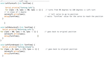
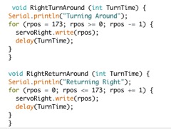
Once I had one subroutine working, I was able to use the first one as a template for the rest. The whole list is shown below.
Figure 5: List of Subroutines
After creating our subroutines, we are finally able to jump into our main loop where each of the servo subroutines will be called. For the final mission, the BiPed will be commanded via Bluetooth. But for testing purposes only, I will be using the serial monitor to input commands. There are many ways to do this, but for simplicity I will be using the switch-case method, where certain letters will be translated into certain functions. The loop is shown below.
Figure 6: Main Loop
From the lower half of the screenshot you can see case ‘f ‘: LeftTurnLeft. This means that when ‘f ’ is typed into the serial command window, it will call the LeftTurnLeft subroutine with a delay time of 20 milliseconds. I cut off the rest of the cases but it continues to list every correlation between input letters and their subroutine.
Finally, after creating all of the subroutines and command inputs, it was time to test it out. Using the same connections that were laid out before, with the control pin connected to digital pin 9, I sent the commands through the serial monitor and verified the result.
Figure 7: Serial Monitor
It works! Not only did the servo follow the command, but the result is also displayed on the window. To test the right leg I just moved the control pin from digital pin 10 to digital pin 9 on the Arduino.
Conclusion
We were able to test all sorts of turning and verify that for our needs of the game and our mission objectives, we will be able to achieve mission success.


