Spring 2017 BiPed – Working Prototype/Walking and Balancing Experiment
By: Alexander Clavel (Project Manager)
Approved By: Alexander Clavel (Project Manager)
Table of Contents
Introduction
This post will cover an updated design of the last prototype as there were issues with functionality and acceptability by the customer. From the last design we had, it did not account for shifting the center of mass at all and had no way to balance its self during each step. Instead it used overlapping feet in which case was pointed out by the customer as unacceptable. This new design incorporates a similar gear box as the last with modified feet and an added balancing system.
New Design
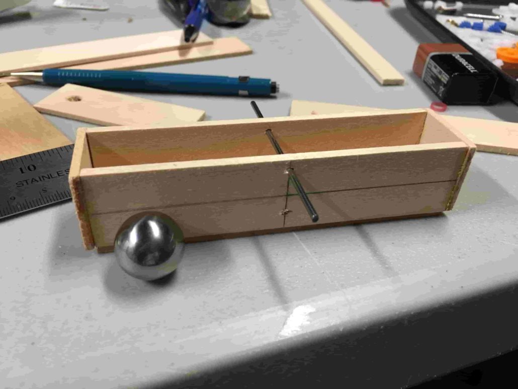
Figure 1
The main difference between with the new prototype is the ability to shift its center of mass. That was also the main issue with the customer as he pointed out the sloppy and sluggish walking movement of the last prototype. Figure 1 shows what the new design is centered upon which is a tilt box with a moving ball bearing. The idea behind it is that as the BiPed takes each step, the box will tilt and roll the weighted ball to shift the center of mass onto the other foot. Timing was a big issue with this design as the mass had to be shifted just as the opposite foot was being planted to become the main support. If it was done too early or too late then the robot would have fallen over.
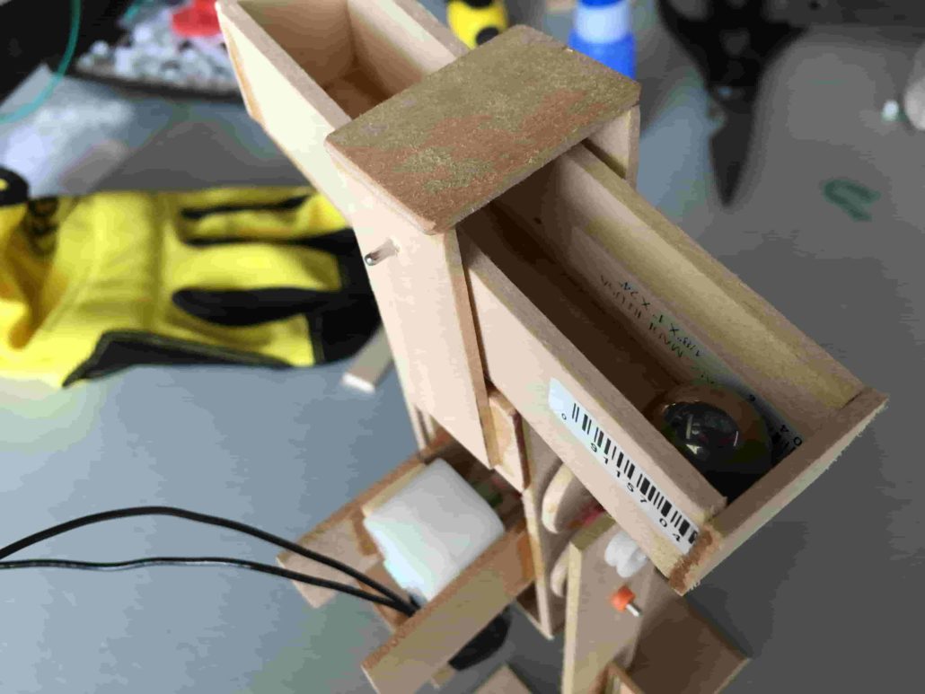
Another central design change is that instead of putting the DC motor slightly to the side, I put it directly into the middle as shown in Figure 3 below. This plays an important role in keeping the center of mass in the center and making it easier to shift the mass from one foot to the other. In this entire system as shown in the picture, the DC motor is what takes up most of the weight. As it is, the entire system weighs less than 200 g. What this means for the robot is that most of the weight is placed lower to the ground. This makes it easier to achieve static walking and keeps it more balanced as opposed to placing most of the weight at the top.
Method of Balancing
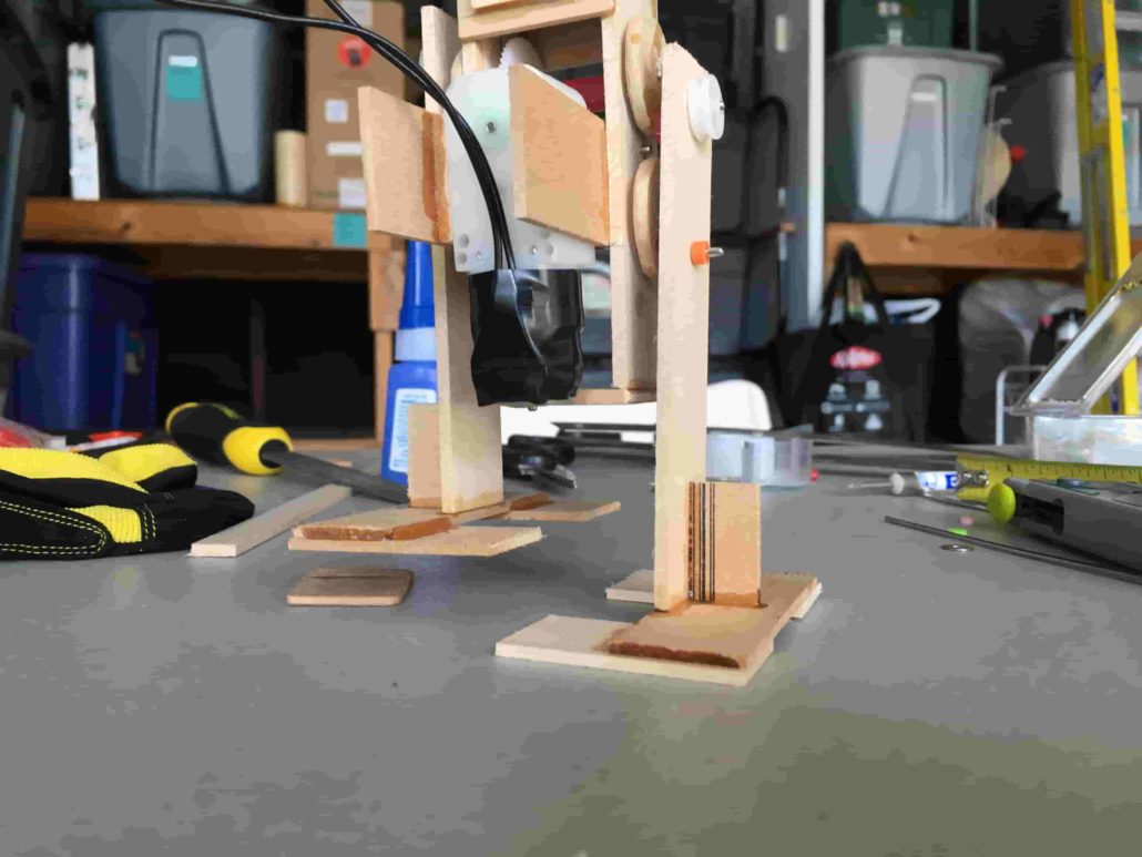
Figure 3
Figure 4
Figure 2 and 3 shows how the robot would stand on one foot to stay balanced. In figure 2, the box is shown to be tilted and in which case the ball bear is sitting on the left side (right side of the picture) of the robot allowing it to stand only on the left foot. Figure 4 shows the placement of the bearing when shifting to one side. The feet in the images are a “C” shaped configuration, but it should not be confused with overlapping as in the last prototype. It is to be noted that the shape of the foot could be manipulated very easily, but for the sake of testing how balanced it would be, they were made to be large enough to be certain that it would cover wherever the center of mass shifted to.
This was the starting point to moving forward with the product. There are requirements stating that the BiPed should be able to statically walk which by definition is being able to maintain it’s balance throughout each stage of its walking. It should also still be able to stay upright even when power is shut off. This design evidentally works as shown in the pictures as there is not power attached to the robot but still is able to remain standing.
Walking & Static Balance Experiment
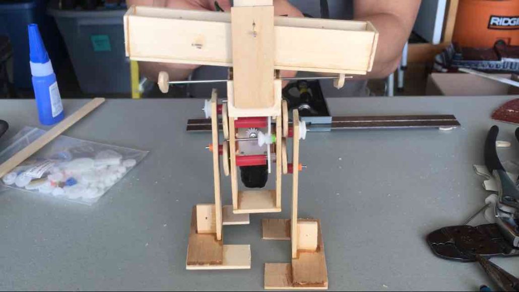
The design as shown in the figures above was not enough to keep it walking continuously. There was another CAM that was needed to be able to tilt the box back and forth. The completed prototype and design is shown in Figure 5 below.
Figure 5
Figure 5 shows the Biped in mid step as it starts to lift up its right foot (left side of the picture) and starting to shift its weight. The leg CAMs and the box CAM are all connected through to the same motor and share the same gear ratio so that the rotational speed is synced perfectly. As the feet are turning, the small pegs on the long metal shaft are rotating at the same rate. The position of the pegs is what allows for the shifting of the weight at the opportune moment. As a peg completes a rotation, the more elongated part of the peg will make contact with the box and tilt it up inevitably rocking the ball bearing to the opposite side. This took much trial and error to find the optimal positioning.
Once the optimal position was found, I connected the motor to the battery and let it run freely. The result was that it walked exactly as I wanted it and it was able to stay stable throughout the entire walk. Here a short video can be found as to the actual walking footage and balancing test.
Conclusion
In the end, static walking had been achieved but can still be improved on. The robot is able to statically walk but the inertia of the moving ball does seem to have a slight affect on the robot as it rocks the biped slightly. It is still able to walk in a straight line but it can be improved upon. The final design should include something to dampen the ball bearing like perhaps a sponge or spring as to soften the momentum. This should prevent the robot from any sort of falling due to any kind of sideways momentum.


