Spring 2017 Mini Pathfinder Encoder Testing
By: Moses Holley (Electronics and Control)
Table of Contents
Introduction
The objective of this test was to gain an understanding of how RPM encoders work along with the Arduino code to manipulate them. We need the shaft encoders to detect wheel slippage and control the differential turning for the Mini Pathfinder.
Subsystem Relation
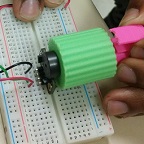
The RPM encoder test was first implemented using the OSEPP Motor Encoder. In this test, We gained an understanding of how the two A3144 hall effect sensors on the chip detect the rotating magnets. Then with the Arduino code converts the rotations in to RPMs. This test was used to measure the speed at which the wheels will turn at the 3dot output voltage of 5 volts. The n20 motors are rated at 6v at a speed of 32 rpm. We used an Arduino Uno because the 3Dot was having trouble uploading at the time.

Figure 1. Test Setup

Figure 2. RPM output
Arduino Code
Average RPM reading Code: This code waits for 10 readings then gets the avg of the RPMs.
// read RPM and calculate average every then readings.
// This code was retrieved online and we manipulated the reading[index] to get the correct readings.
const int numreadings = 10;
int readings[numreadings];
unsigned long average = 0;
int index = 0;
unsigned long total;
volatile int rpmcount = 0;//see http://arduino.cc/en/Reference/Volatile
unsigned long rpm = 0;
unsigned long lastmillis = 0;
void setup(){
Serial.begin(9600);
attachInterrupt(0, rpm_fan, FALLING);
}
void loop(){
if (millis() – lastmillis >= 1000){ /*Uptade every one second, this will be equal to reading frecuency (Hz).*/
detachInterrupt(0); //Disable interrupt when calculating
total = 0;
readings[index] = rpmcount * 5.45; /* Convert frecuency to RPM, note: this works for one interruption per full rotation. For two interrups per full rotation use rpmcount * 30.*/
for (int x=0; x<=9; x++){
total = total + readings[x];
}
average = total / numreadings;
rpm = average;
rpmcount = 0; // Restart the RPM counter
index++;
if(index >= numreadings){
index=0;
}
if (millis() > 11000){ // wait for RPMs average to get stable
Serial.print(” RPM = “);
Serial.println(rpm);
}
lastmillis = millis(); // Uptade lasmillis
attachInterrupt(0, rpm_fan, FALLING); //enable interrupt
}
}
void rpm_fan(){ /* this code will be executed every time the interrupt 0 (pin2) gets low.*/
rpmcount++;
}
RPM Code: This code gets the RPM of each reading.
// read RPM
// This code was retrieved online and manipulated the RPM.
volatile int rpmcount = 0;//see http://arduino.cc/en/Reference/Volatile
int rpm = 0;
unsigned long lastmillis = 0;
void setup(){
Serial.begin(9600);
attachInterrupt(0, rpm_fan, FALLING);//interrupt cero (0) is on pin two(2).
}
void loop(){
if (millis() – lastmillis == 1000){ /*Uptade every one second, this will be equal to reading frecuency (Hz).*/
detachInterrupt(0); //Disable interrupt when calculating
rpm = rpmcount * 5.45; /* Convert frecuency to RPM, note: this works for one interruption per full rotation. For two interrups per full rotation use rpmcount * 30.*/
Serial.print(“RPM =\t”); //print the word “RPM” and tab.
Serial.print(rpm); // print the rpm value.
Serial.print(“\t Hz=\t”); //print the word “Hz”.
Serial.println(rpmcount); /*print revolutions per second or Hz. And print new line or enter.*/
rpmcount = 0; // Restart the RPM counter
lastmillis = millis(); // Uptade lasmillis
attachInterrupt(0, rpm_fan, FALLING); //enable interrupt
}
}
void rpm_fan(){ /* this code will be executed every time the interrupt 0 (pin2) gets low.*/
rpmcount++;
}
// Elimelec Lopez – April 25th 2013
Conclusion
Although we gained a lot of understanding of how the RPM encoder works we will not use this model for our design. The shape of the OSEPP encoder is catered to a DC motor placed of it to be very close to the rotating magnets. We will have a different design that has the DC motor encased in the wheel which requires that the rotating magnet rotate around the motor. When we decide what kind of encoder will be used there will be an updated blog post.