Spring 2017 SpiderBot : Firmware Blog Post
By Shaun Pasoz – Electronics & Control Engineer
Introduction
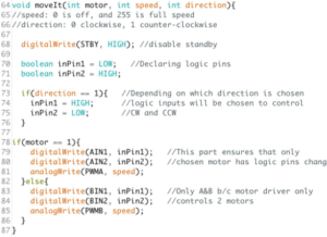
While waiting for the breakout boards to come in the mail, to make the best use of time the E&C division manager tasked us with coding quizzes. One of the quiz questions involved controlling the TB6612FNG motor driver using a microcontroller such as the Arduino UNO. Below is the snippet of code submitted for that quiz question along with the comments:
In order to allow easy calling of the functions for the MST engineer the moveIt() function was itemized into corresponding functions as follows: a forward move, backward move, left turn, and right turn. An example of the forward() function is demonstrated below:
This code displayed above allows for control of two motors by utilizing four digital pins and two PWM pins from the microcontroller all from the same function. From here the next step was to include the code to control the third motor that will be controlling the winch.
Since the 3DoT only has pins available for two motors, it was necessary that the third motor be controlled via I2C. After doing some research it became evident that the Adafruit Motor Shield V2 used the same primary ICs as our PCB. To avoid writing code to manually control the I2C protocol the Adafruit Motor Shield library was used. The following snippets of code demonstrates our implementation of the Adafruit Motor Shield library:
Conclusion
To summarize, the motor shield object is instantiated using the Adafruit library with an address of 0x60. Motor 1 is then instantiated (since our project only needed one motor to be controlled only one instance of the object is instantiated), where the logic pins AIN1, AIN2 and PWMA from the TB6612FNG IC is connected to PWM pins 0, 1, and 2 on the PCA9685 chip. In order to allow for this the Adafruit library .cpp file was changed such that AFMS.getMotor(1) corresponds to PWM pins 0, 1, and 2.
The object is then began in the setup function and STBY pin on the TB6612FNG IC is brought HIGH by setting PWM pin 15 to a 100% duty cycle. Furthermore, the winch motor is set to full speed since the system utilizes 3.3V to power the motor, full speed is adequate for all instances of the winch motor control. Lastly, the equivalent move function of the winch motor is itemized in a function, called goUp(), to easily be called by the MST engineer when programming Bluetooth communication.


