Spring 2017 SpiderBot : Prototyping Blog Post
By Shaun Pasoz – Electronics & Control Engineer
Introduction
Before sending out the PCB design for production, it is necessary to prototype the design using breakout boards and through-hole components. This is a necessary step to test the components in combination with the code and make sure the design works. The purpose of our PCB is to allow control of a third DC motor using the 3DoT. Our design utilizes two IC’s: the TB6612FNG manufactured by Toshiba, and the PCA9685 from NXP Semiconductors.
The TB6612FNG is a dual H-bridge motor driver. It will be used in our PCB design to control the third DC motor. The pins utilized on the motor driver will be VM, VCC, AIN1, AIN2, PWMA, STBY, AOUT1, and AOUT2. The PCA9685 is an I2C compatible 12-bit PWM driver. Since the 3DoT provides no PWM enabled digital pins, the component is necessary in the PCB design to provide PWM to the motor driver. The extraneous PWM pins will be used as a digital signal to control the motor driver.
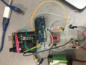
Seen below is a Fritzing diagram of our design alongside a picture of the actual implementation:
Figure 1: Breakout Board Fritzing Diagram
Figure 2: Image of Implementation of Breakout Boards
In an effort to avoid soldering and de-soldering leads to the breakout boards, the implementation is not as clean. The implementation also shows that the design can easily be powered from a separate power supply; in this case, a 9V battery.
Update:
Although the design works using breakout boards. When implemented on a PCB, the PCB did not work. This could be due to a couple reasons. One, it’s possible the IC’s got damaged in making the PCB as it was not built in an ESD safe lab. Two, it’s possible that there was a manufacturing error such as traces being placed too closely together, or traces poor insulation of the traces. The second choice is the suspected problem as we tried making three different boards, using new IC’s and testing both ceramic and tantalum capacitors.


