Spring 2018 3DoT Hexy: Assembly (Prototype/Final)
By: Eduardo De La Cruz (Project Manager & Manufacturing Engineer)
Approved by: Miguel Garcia (Quality Assurance)
Table of Contents
Introduction
The purpose of this blog post is to demonstrate how all parts designed in Solidworks were put together along with other outsourced materials. We will be assembling two models of our robot: the prototype which is based of our preliminary design review design and our final design which can be found in “Spring 2018 3DoT Hexy: 3D Model”.
Related Requirements
C-03:
The robot will be designed to be a toy for people ages 8+.
C-04:
In order to minimize manufacturing cost, and packaging cost the robot shall be able to be constructed from sub assemblies within 10 minutes.
Assembly of Final Model – (May 07, 2018)
Parts
3D Printed Parts:
- x1 – Sensor Enclosure
- x1 – Hardware Enclosure
- x1 – Top plate
- x1 – Bottom plate
- x1 – Cable tube
- x2 – Left Femurs
- x2 – Right Femurs
- x2 – Middle Femurs
- x6 – Tibias
- x6 – Femur-to-gear
Components Outsourced:
- x22 – 3 -.5 mm nylon lock nuts
- x6 – 3 -.5 mm hex nuts
- x10 – 3 -.5 mm x 16 mm flat head machine screws
- x12 – 3 -.5 mm x 20mm Socket cap screws
- x6 – 3 -.5 mm x 16mm Socket cap screws
- x12 – 8 mm x 4 mm OD x 3 mm ID aluminum bushings
- x10 – 3 mm ID brass plated bushings
- x16 – 3mm x 6mm (ID/OD) (#4) washers
- x10 – 3mm x 8mm (ID/OD) (#6) washers
- x4 – 3 -.5 mm x 45 mm socket cap screws
- x4 – 1’ x ¼ ‘’ OD nylon spacers
- x2 – Actobotics micro gear motor enclosure
- x6 – 30T Ajax Scientific plastic gears
- x4 – 10T Ajax Scientific plastic gears
- x2 – Driving gears
- x2 – 530 RPM micro gear motors
- x10 – VxB 3 x 6 x 2.5 mm bearings
Required tools:
- Philip Screw Driver
- 3 mm hex nut driver
- 3 mm allen key
Steps
Note: The leg assembly, which is the tibia, femur and gear will be advertised as a single piece to reduce assembly and disassembly times. However, for the purpose of this blog post we will go through the leg assembly for reference purposes.
Leg Assembly
Step 1: Connect the tibia to the femur and fasten them using a 20 mm socket cap screw and a hex nut.
Step 2: Connect the femur-to-gear joint to the gear and fasten them together by running a 16 mm socket cap screw with a #4 washer through the bottom of the gear and fasten them together using a lock nut.
Step 3: Connect the other end of the femur to the gear-to-femur joint using a 20 mm socket cap screw and a lock nut.
Step 4: Adjust how tight each screw is to achieve the best movement
Final Assembly
Step 1: Run a 16 mm flat head machine screw through the bearing bore of the gear, add a brass bushing and a washer through the other end of the screw, and fasten this assembly to the chassis using a lock nut and #6 washers.
Step 2: Connect the legs to the chassis leg guides
Step 3: Connect the top plate to the bottom plate using 45 mm socket cap screws, 1 inch spacers, and lock nuts.
Step 4: Connect the sensor enclosure to the chassis by using the same 45mm socket cap screws to one end of the chassis.
Step 5: Attach the motor enclosure to the bottom plate.
Step 6: Attach the cable tube to the back using the custom mount fabricated and using a 3 mm screw.
Step 7: Place the hardware cover which should clip on by the use of magnets.
For instructions on installing the hardware, reference the system integration and testing post.
Final Assembly
Assembly of Hexy Mk-01 (Prototype) – (April 3, 2018)
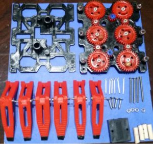
Figure 1: 3DoT Hexy Mk-01 Parts
Parts
3D Printed Parts:
- x1 Bottom Plate
- x1 Top Plate
- x2 Left Femur
- x2 Right Femur
- x2 Middle Femur
- x2 Middle Tibia
- x4 Outer Tibia
- x6 Femur-to-Gear joint
Components:
- x6 cotter pins
- x10 3-.5 mm nylon lock nuts
- x4 3-.5 mm hex nuts
- x6 2.5 x 15 mm machine screws
- x10 3×15 mm machine screws
- x4 3×30 mm machine screws
- x4 3.5 x 15 mm sheet metal screws
- x6 30T Ajax Scientific plastic gears
- x4 10T Ajax Scientific plastic gears
- x2 10T Driving gears
- x2 530 RPM micro gear motors
- x2 Actobotics micro gear motor enclosure
- x6 5×2 mm sheet metal screws
- x4 20 mm x 3.5 mm (length/inner diameter) spacers
- x6 3 mm x 10 mm (inner/outer diameter) washers
- x4 3 mm x 6 mm (inner/outer diameter washers)
Required tools:
- Philip Screw Driver
- 3 mm hex nut driver
- Flat tip pliers
Recommended:
Figure 2: Lucas Red “N” Tacky
Adding Lucas Red “N” Tacky grease before inserting gear shaft screws and to the gears themselves improves the performance of the cam system by reducing friction between parts.
Steps
- Connect femur-to-gear joint to gears. Insert 5×2 mm sheet metal screws into designated gear hole. Connect joint to gear by screwing it in until the joints bottom face comes in contact with the gear.
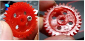 Figure 3: Assembling gear-to-femur joint
 - Place Washers and gears over gear holder holes. Note 3 x 10 mm washer go on 30T gears and 3 x 6 mm washers go on 10T gears.
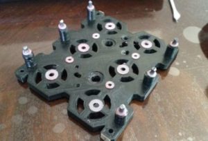 Figure 4: Placing washers
 - Insert 3×15 mm machine screws and place nylon lock nuts on the underside. Screw in nylon lock nuts, using 3 mm hex nut driver, to a desirable position that is not to tight to prevent gear rotation. Note: Adding grease to screw shaft and gear improves cam performance.
 Figure 5: Placing gears, screws, and lock nuts
 - Assemble legs. Mate the femur to the tibia to form elbow joint. Insert 2.5×15 mm machine screws to hold joint together.
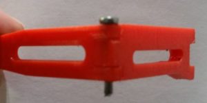 Figure 6: Assembling legs
 - Adding legs to cam system. Connect legs to femur-to-gear joint using cotter pins. After inserting cotter pins use flat head pliers to pry open the endpoints of the cotter pins.
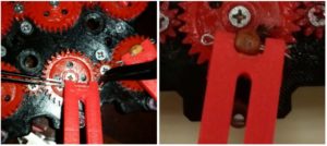 Figure 7: Adding cotter pins
 - Insert micro gear motor enclosures to the underside of the bottom plate and screw them in place using 3.5 x 15 mm sheet metal screws.
 Figure 8: Adding micro gear motors
 - Insert 10T Driving gears from the top plate and insert micro motors from the bottom plate. Since we are using the method A driving gear design (read above) we will need to apply a little pressure to insert gear with bushing into the shaft of the motor.
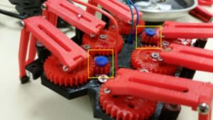 Figure 9: Adding driving gears
 - Insert femur’s center opening on the aluminum rods (as shown above)
- Place top cover, align it with the bottom plate, insert 20 mm spacers in each corner, insert 30 mm machine screws in each corner, and screw hex nuts to screws from the underside of the bottom plate.
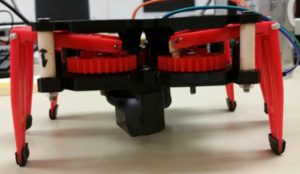 Figure 10: Adding spacers, screws, and hex nuts
 - Run motor wires to the top plate.
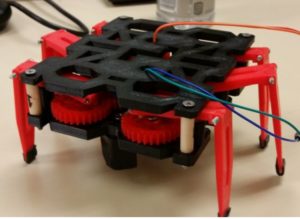
Assembled Prototype
Resources

