Spring 2018 3DoT Hexy: Booster Shield Layout
By: Kris Osuna (Electronics & Control Engineer)
Verified by: Eduardo De La Cruz (Project Manager and Manufacturing Engineer)
Approved by: Miguel Garcia (Quality Assurance)
Table of Contents
Introduction
3DoT Hexy needs to have a 5V source to power the micro metal gear motors and UV LEDs. We are using a booster to get 5V from a 3.7V battery source. Using the software Eagle CAD and the TI WEBENCH tool a schematic and PCB is being made. The original booster we purchased used a 9-ball grid array. This caused a lot of problems. Placing the chip on the PCB editor showed that it starts with clearance errors. This is due to the balls being so close to each other. With Professor Hill’s advice I approved all clearance errors and moved forward.
Requirements
- Must have an output voltage of 5V and an output current of 1.1A
Materials
- Eagle CAD software
- TI WEBENCH interactive tool
Update 3 (April 19, 2018)
We will no longer be using a booster shield for a variety of reasons. 3DoT Hexy has been improved and can move with the load at 3.7V. We will no longer be using the UV LEDs at 5V instead we will be using IR LEDs at 3.3V.
Update 2 (April 13, 2018)
We changed the booster package to a SMD chip. The PCB board was made with no errors and awaits final approval.
 Figure 1: Booster shield with the SMD chip produces no errors.
Update 1 (April 13, 2018)
The Eagle CAD DRC check kept producing errors. Placing polygons on the connecting balls resulted in error. Placing routes at different angles produced errors. Placing a route with the minimum width of 10 provided errors. We are looking at different solutions for this problem.
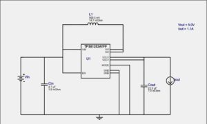
Figure 2: The TI WEBENCH interactive picture provided the schematic to use and even provided an Eagle CAD schematic file.
We were able to find the dimensions of a blank 3DoT board, as a reference for our PCB design:
Link to
The current PCB still being worked on due to errors, nevertheless, we have provided a preliminary design of our schematic and PCB. The finished schematic and PCB will be uploaded when they are finished.
 Figure 4: Booster Shield Schematic
 Figure 5: The dimensions of the blank 3DoT PCB shield were obtained and used for our PCB


