Spring 2018 3DoT Hexy: Decision of Movement Mechanism
By: Eduardo De La Cruz (Project Manager and Manufacturing Engineer)
Approved by: Miguel Garcia (Quality Assurance)
Table of Contents
Introduction
Taking into account the level 1 requirement of using only 2 micro motors to drive the movement of the robot, and by using designs from previous semesters as a reference. We as engineers had to determine the most optimal mechanism that would take full advantage of the 2 micro motors. References, such as that of Spring 2016: 3DoT Spider-Bot Mechanism Research, pretty much covered the most promising designs to implement using 2 motors. However, we decided to focus more on the two models that were successfully built in the past: the Klann Linkage mechanism of Spring 2017’s Spiderbot, and the Hex Bug 2 mechanism Spring 2016. The goal we wish to accomplish by picking from the former or the latter is to: reduce the amount of time invested in researching new designs, increase the probability of success, and invest more time building on improving existing designs.
Related Requirements
- To keep cost down, and keep a toy aspect , the robot shall use only 2 micro motors to drive the movement of the robot.
- The robot will need to navigate remotely through a custom built maze (built by AoSa image), memorize the path it took, start over, and autonomously travel through the path it took.
- The spiderbot shall have an allocated budget of $250, however to compete with the existing robot toy market we shall try to minimize the cost of production as much as possible.
- In order to minimize manufacturing cost, and packaging cost the robot shall be able to be constructed from subassemblies within 10 minutes.
- For quick production of the prototype, the preliminary project shall be restricted to six hours of total printing time with a 2 hours limit for each single print.
Design 1: Spring 2017 SpiderBot, Klann Linkage Mechanism
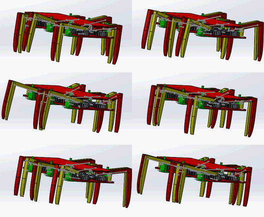
Figure 1: Klenn Linkage Mechanism
Eight legged Klenn linkage spiderbots follows a 4 inner and 4 outer rule for stability. This means that the spider will always have 4 points of contact: Case 1: outer legs lift and inner legs thrust, and Case 2: inner legs lift and outer legs thrust.
Pros:
- Parts can be fabricated using laser cutter, reducing our 3D print times
- Design will have 8 legs like an actual spider due to the need of bilateral symmetry
- Design can be implemented using 2 motors
- Can turn in place if programmed correctly
Cons:
- A lot of parts will increase weight of the robot
- The width of the robot will need to increase in order to fit 3DoT board and all components in the middle.
A lot of resources on this model can be found online. Below are links to a couple of useful references on the Klann Linkage mechanism.
- How it works
- Two Motor controlled Klann Linkage mechanism that can turn
- Going over objects
- Movement Dynamics
- Sample model built from start to finish
Design 2: Spring 2016 3DoT David, Hex Bug 2 Mechanism


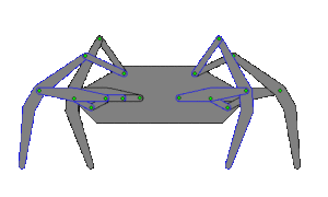
Figure 2: Hex Bug Mechanism
This design can be accomplished using a cam system and by configuring the legs to move either as:
Shown above:
Case 1: Outer 4 legs lift, inner 2 legs thrust
Case 2: Inner 2 legs lift, Outer 4 legs thrust.
Design requires small lift height, in order to reduce time outer legs remain of the ground for stability.
Or:
can be reconfigured by adjusting the position of the legs on the gears to follow a tripod motion(as shown below).

Figure 3: Tripod Movement
This was what Spring 2016s 3DoT David design had to do, click here.
Pros:
- Design looks simple, not as many parts compared to Klenn linkage model
- Can be designed to be small and compact because 3DoT board and other components can be placed over the mechanism without interfering leg movement .
- Can turn if properly programmed, as demonstrated in the Spring 2016 video.
- Can be driven using only 2 motors
- A lot of components can be made with either 3D or laser cutter.
- Uses only 6 legs which reduces weight and cost of manufacturing.
Cons:
- Leg to floor clearance during lift will be small, therefore, won’t be able to go over big objects
Resources:
- https://www.arxterra.com/spring-2016-3dot-spider-mechanism-research/
- http://robotics.hobbizine.com/knexapod.html
Final Design Decision
Having had studied both design more in depth we decided that implementing the Hex Bug 2 design was the way to go. The Hex Bug 2 design takes advantage of gears configured as a cam system to provide sufficient torque to the legs for movement. This will reduce amount of 3D components needed since we will most likely be able to purchase gear set from an online retailer. Also this design only requires 6 legs meaning we will have less weight and less 3D printed parts to worry about. The only components that will most likely need to be 3D printed will be the femurs, and tibias. The chassis will most likely be laser cut. Since we need to fit the robot in small maze rooms, current maze rooms are 3’’x3’’, the Hex Bug 2 design allows us to make everything small and compact because we can place the 3DoT board and other components on a platform over the gear mechanism without interfering leg movement. The issue of floor clearance during lift won’t be an issue because going over objects is not a mission requirement.

