Spring 2018 3DoT Hexy: Determine Gear Design
By: Eduardo De La Cruz (Project Manager and Manufacturing Engineer)
Verified by: Eduardo De La Cruz (Project Manager and Manufacturing Engineer)
Approved by: Miguel Garcia (Quality Assurance)
Table of Contents
Introduction
Since we are going to base our design of Spring 2016 3DoT David, we will need to implement a functional cam system that is either similar or better in design then that constructed by the Spring 2016 team. In this blog post we will: go over current gear ratio from existing 3DoT david cam system, determine the cam system design for Hexy, potential driving and driven speeds for our design (based on motor selection), go over the gears we will use , and implementation.
Related Requirements
- To keep cost down, and keep a toy aspect , the robot shall use only 2 micro motors to drive the movement of the robot.
- The robot will need to navigate remotely through a custom built maze (built by AoSa image), memorize the path it took, start over, and autonomously travel through the path it took.
- The robot shall operated in a tripod form, having three legs (2 outer in one side and middle leg in the other side) to provide stability while moving.
Update (March 15, 2018)
We decided that pursuing a 3:1 configuration would be the way to go. This is due mainly to the femur-to-gear joints. 20T gears have a smaller surface area over which to place joints that need to be made bigger based on assembled prototype.
Trade study (March 6, 2018)
3DoT David’s Cam
Since we were given access to the 3DoT David robot and their blog post research, we were able to analyze the design more in detail. The manufacturing department even went the extra mile to model gears from the robot on solidworks by measuring the pitch diameter, outer diameter, tooth thickness, addendum, dedendum, pressure angle and face width using a digital caliper (click here for meaning of these variables). Below is a model of 3Dot David cam system:
Figure 1: Current cam design
The gear ratio for 3DoT David’s cam is 3:1. The small gear has 10 teeth with a pitch diameter of 10 mm and the big gear has 30 teeth with a pitch diameter of 30 mm. The driving gear (where motor connects) is the lower left blue gear. According to, Spring 2016: 3DoT David Gear Train , 3DoT David is designed to drive the larger gears at 2 rev/sec, therefore, the driving speed of the motor should be 360 RPM. The 3DoT David team decided that it would be best to use geared motors rated at 450 RPM at 6V and use a booster shield to reach 5 V to get to 360 RPMs for the input gear (click here to read more on how they determined this motor choice). A video of 3DoT David cam performance can be seen by clicking here .
The cam system we will use
So far two potential cam designs are going to be used to experiment on. The first one will be 3DoT David’s 3:1 configuration, and the second one will be a 2:1 configuration shown below:
Figure 2: Alternative design
For this configuration we would use small gears with 10 teeth and large gears with 20 teeth. Since gears sizes are scaler, modeling 20 tooth gears from 10 tooth gear, generated above, was not an issue. The reason for using this configuration is that it would reduce length of 3DoT Hexy by 6 mm from 3DoT David design, and reduces length of femurs that would connect to the red gears. This document will be updated when we determine the configuration we go with for our cam system.
Required Driving and Driven Speeds for our design choice, under ideal conditions
Note: Driving Gear (G1) = small gear connected to motor.
Driven Gear (G2) = large gear used to move legs.
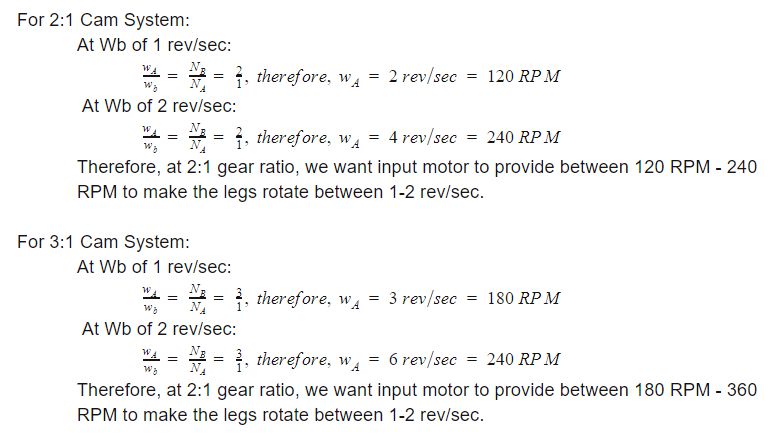
For the most part we want our robot to rotate its legs anywhere between 1 and 2 rev/sec. Therefore we will calculate speeds for 1 and 2 rev/sec for 3:1 cam system, and 2:1 cam system, both shown above. Calculations were done using Gear train document as a reference from wikipedia.
Note: G1 speed = Wa, and G2 speed = Wb
Na = teeth on G1, and Nb = teeth on G2
 Figure 3: Calculation for different cam configurations
The Gears we will use
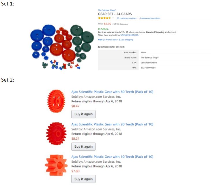
There are two methods of obtaining gears for our cam system: buying or fabricating gears. After consulting with Prof. Hill over the possibility of fabricating gears, Hill recommended we just pursue purchasing gears. Therefore, the manufacturing department went on a hunt for purchasable gear sets. Taking into account that we need gears with 10, 20, and 30 teeth to model our two configurations and the source material on gear instability done by the 3DoT David team we found the following two gear sets on Amazon:
Both sets have the desired pitch diameters of 10, 20 ,and 30 mm. The advantage of picking Set 2 is that it will be the same gear set that 3DoT David used.
In case these gears don’t work, we always have the gears the manufacturing department accurately created from scratch using solidworks for CNC cutting:
Figure 5: Gear generated in Solidworks
Note:
These gears cannot be found in Solidworks libraries. These models were accurately obtained by determining the pitch diameter, outer diameter, tooth thickness, addendum, dedendum, pressure angle and face width using a digital caliper and using 3DoT David’s Gears as a reference.
Files for these gears can be found below:
How final design would look with legs connected
3:1 System:
Figure 6: One side of assembled cam
This design will be mirrored along the vertical axis and femurs will be positioned in opposite order of the ones above: outer legs in an middle leg out to have 3 legs on the ground at all time for balance (tripod).
Note:
2:1 system will have the femurs connected to the red gears and would be positioned in the same way as above .
Conclusion
Currently we are more interested in pursuing the 3:1 cam system for our design, however, we will attempt to model the 2:1 system to see if it would be better for our design instead of 3:1. We will update this document after the rapid prototype has been made modeling both gear designs. From this blog post our E&C was able to determine motor selection based on the gear calculations above. We will be using a 530 RPM at 6 V high torque micro gear box motor, will see RPM rating at 3.7 V (battery rating) and determine whether or no we need a boost shield to drive the cam system at the desired RPM.
Resources
- https://www.arxterra.com/3dot-david-gear-train/
- https://www.arxterra.com/3dot-david-rapid-gear-instability/
- https://en.wikipedia.org/wiki/Gear_train/


