Spring 2018 3DoT Hexy: Getting 3DoT David Working
By: Kris Osuna (Electronics & Control Engineer) and Eduardo De La Cruz (Manufacturing Engineer)
Verified by: Eduardo De La Cruz (Project Manager and Manufacturing Engineer)
Approved by: Miguel Garcia (Quality Assurance)
Table of Contents
Introduction
Since we will be basing our design of Spring 2016’s 3DoT David, it is important that we get a good idea of how 3DoT Davids mechanism functions, as well as of how this mechanism will be interfacing with the 3DoT board and all attached peripherals. Additionally, getting 3DoT David working will enable us to find areas that can be improved upon and may be applied as solutions in the development of our prototype. We will divide this blog post into two sections: 1. What was done by the manufacturing department and 2. What was done by E&C department.
Related Requirements
Level 2 Requirement
The robot will use a cam system identical to that of 3DoT David to drive the movement of the legs while navigating through the maze.
Manufacturing
By: Eduardo De La Cruz
Minor Repairs
Replaced Driving Gears
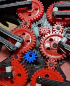
 Figure 1: Added blue gears with D shaped bore
The previous driving gears (gears tied to motor shafts) where not turning the cam system. Therefore, a solution that the manufacturing department came up with was using gears with a smaller bore diameter and creating a D lock bore to prevent the gear from slipping from the motor shaft. As seen above by the blue gear.
Replaced a gear shaft with a screw
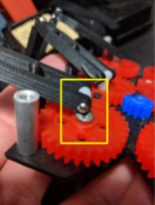
 Figure 2: Added flat head screw as a replacement gear holder
The current gear shafts are 3D printed and are very thin and fragile. A good replacement for this is a 3 mm screw with a hex nut holding it in place. To prevent the thread of the screw from messing up the gear bore, we sanded down the thread.
Added grease  Figure 3: Red “N Tacky Grease
The gears were having a hard time turning and would often lock. An attempt to fix this issue was to add Lucas Red “N” Tacky grease between the gears. Doing this actually improved cam system performance.
Conclusion
- Need rubber tips or other material for leg tips, to prevent slipping when walking.
- Needs better gear capture system. Current system is permanent (melting plastic gear shafts) which defies the current requirement of assembly and disassembly.
Figure 4: Melted Gear shafts
- Gear shafts are very fragile and can easily break. (Should pursue alternative solution than 3D printing gear shafts).
- Need to isolate wires from cam system. Wires susceptible to getting caught in gears
 Figure 5: Exposed Wires in cam
- Driving Gears often slip from motor shaft. Due to white insert not keeping motor shaft stiff enough.
 Figure 6: Current driving gears in 3DoT David
- To reduce friction between gear shafts and gear bore, it would be interesting to pursue alternative methods to make the gears rotate with less friction, such as using bearings and bushings.
Electronics & Control
By: Kris Osuna
Since the purpose of 3DoT David was laser tag, we were unable to put to good use the custom PCB that was designed by the team. Along with this issue there was also the issue of not having a 3DoT board to interface with. As a result, the Arduino Leonardo microcontroller board was used. The Leonardo was used because it is based on the ATmega32u4, which the 3DoT board uses as well. The Arduino Leonardo technical specifications can be found under references
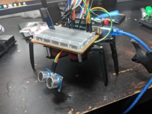
E&C attached the hardware that is used in the lab sequence robot to see if it could walk forward, in reverse, and turn around. The ultrasonic sensor was also placed on the board as well to test for obstacle detection. The bluetooth HC-06 was placed on the board to check for connectivity.
E&C tested operation of 3DoT David lab sequences 1 and 2. We were able to get 3DoT David to walk straight, turn right, turn left, detect obstacles and be controlled via a cellphone with bluetooth. The software can be found under links.
 Figure 8: 3DoT David with all hardware from the lab sequence robot
Conclusion
The sensors we have purchased work and can be implemented on a microcontroller using an ATmega32u4. The schematic and PCB can be made with the knowledge that all the sensors can work together. Wire management is going to be an issue because the UV sensors, LEDs, and ultrasonic sensors will have to be attached to wires. Manufacturing will be notified of the wire situation to try to find a way to hide the wires. The motor wires are too short and access to the wires is difficult due to being attached to the top plate. Manufacturing will be notified of this problem.
The ultrasound drops the distance reading to 0.0 inches causing 3DoT David to run the same task twice. A condition needs to be put to ignore when the reading drops to 0.0. The Bluetooth commands were not sent through the arxterra website but through a Bluetooth app. This may be due to our Bluetooth not having BLE support. A new Bluetooth module with BLE support was purchased


