Spring 2018 3DoT Hexy: Interface Matrix
By: Raymundo Lopez-Santiago (Mission, Systems, and Test)
Verified by: Eduardo De La Cruz (Project Manager and Manufacturing Engineer)
Approved by: Miguel Garcia (Quality Assurance)
Table of Contents
Introduction
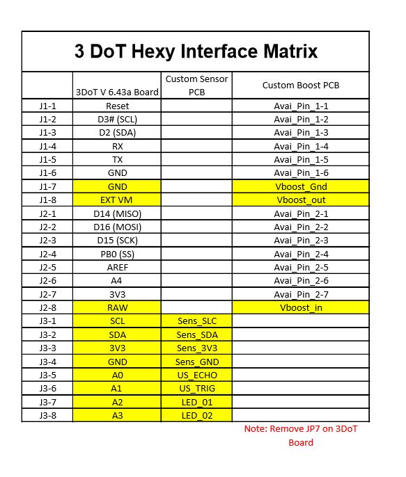
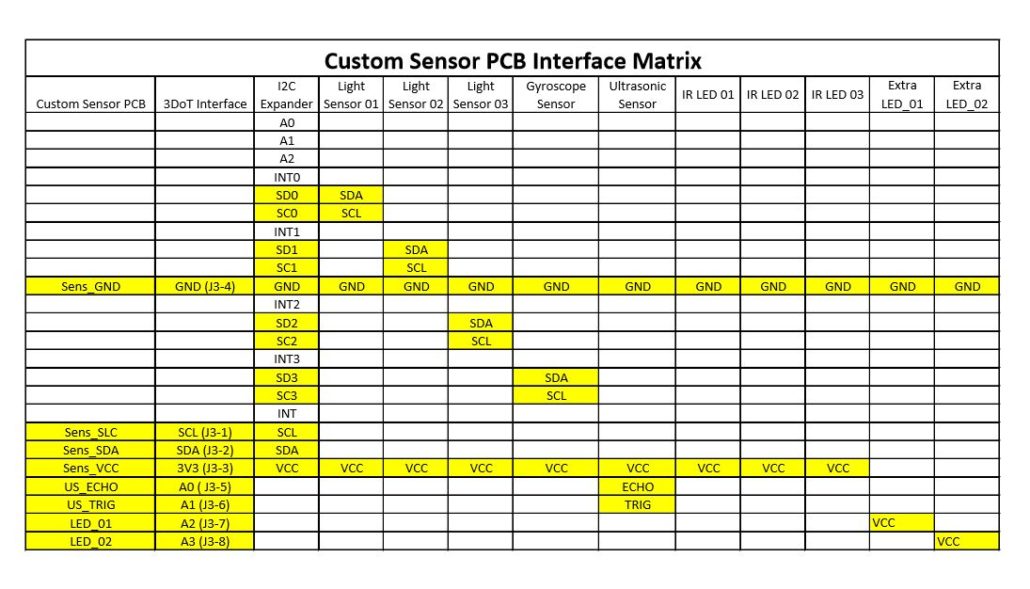
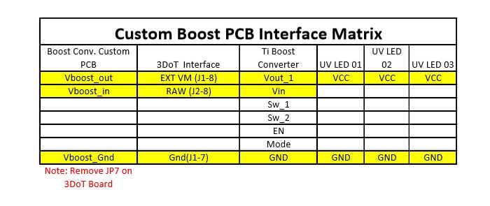
This blog post covers 3DoT Hexy’s final interface matrix. If interested in seeing our preliminary design interface matrix click here. The 3DoT Hexy interface matrix was developed with information obtained from datasheets for each device used and pins allocated from the 3DoT V 6.43a board. Based on our design, we needed to design two custom PCBs, one for all sensors and one with a boost converter to drive our motors as well as power three UV LEDs. To make things easy to understand, the interface matrix is broken up into three interface matrices. As seen in Fig. 1, the main interface matrix relates each custom PCB to the 3DoT board and how each PCB will connect to the 3DoT board. As seen in Fig. 2, the Custom Sensor PCB interface matric further breaks down in detail which sensors will connect to the PCB to make sure no pins are used more than once (except for power and ground). As seen in Fig. 3, the Custom Boost Converter PCB also breaks down in detail which peripherals will connect to the PCB to make sure no pins are used more than once (except for power and ground). After researching different UV sensors, we were unable to find ones that had different I2C addresses, therefore we needed to add an I2C expander to our circuit design. Based on availability and previous semester success, the model I2C expander model used is TCA9548A. The boost converter model used is TPS61253A. The Light Sensor (UV Index Sensor) model used is Si1145. The gyroscope model used is ITG-3200. The Ultrasonic sensor model used is Parallax Ping (a HC-SR04 may also be used).
Related Requirements
Level 1 Requirements
L1-4:
The robot shall have a custom PCB as platform to build from and will incorporate peripherals for sensors
C-12:
The robot shall use a v6.43a 3DoT board.
Level 2 Requirements
L2-2:
The robot shall use a single RCR123A 3.7 V, 650mA rechargeable Li-ion battery to power the 3DoT board, which will power the drivetrain and all attached peripherals.
L2-3:
The robot shall use three Light sensors and three IR LEDs connected to a custom sensor PCB to handle intersection detection.
L2-4:
The robot shall use a Parallax Ping (or HC-SR04) ultrasonic sensor to handle robot avoidance.
L2-10:
The robot shall have (2) LEDs acting as eyes of the spider.
Update 04/24/18
Based on customer concerns with the TPS61253A 9-ball 1.2-mm x 1.3-mm WCSP package, we explored other methods to not use a boost converter and further investigate operating all electronics of the robot at the rated 3.7 V from the RCR123A battery. After improving the gear mechanism with the addition of bearings and bushings, we were able to operate the robot at 3.7V while having stable movement with weight attached on top of the robot (simulating the final weight of all devices used for the final robot configuration). Since this change occurred, we no longer will use any connections from J1 and J2 from the 3DoT board. UV LEDs will no longer be used and will be replaced with IR LEDs. Based on customer recommendation instead of using the 8-channel TCA9548A I2C model, we are going to use a 4-channel model: PCA9544A. All peripheral devices will be connected to the Custom Sensor PCB developed by Kris Osuna (Electronics and Control Engineer). The Custom Sensor PCB is connected to J3 of the 3DoT board. Two additional extra LEDs are added to act as eyes of the spider.
Fig. 1: 3DoT Hexy Interface Matrix
Fig. 2: Custom Sensor PCB Interface Matrix
Fig. 3: Custom Boost Converter PCB Interface Matrix
Conclusion
This blog post covers 3DoT Hexy’s interface matrix. This matrix is composed of the available pins of the 3DoT V 6.43a board and how they connect to each custom PCB. When using the Custom Boost PCB conected to the 3DoT board, Make sure to remove JP7 on the 3DoT board. This will avoid you messing up the 3DoT board. The objective of this document is to allocate pins to components used in the design and make sure no pin is used twice (except power and ground).
References
- https://www.arxterra.com/2016-spring-3dot-david-final-project-blog-post/
- http://www.ti.com/lit/ds/symlink/tps61253a.pdf
- http://www.ti.com/lit/ds/symlink/pca9544a.pdf
- https://cdn-shop.adafruit.com/datasheets/Si1145-46-47.pdf
- https://www.sparkfun.com/datasheets/Sensors/Gyro/PS-ITG-3200-00-01.4.pdf
- https://cdn.sparkfun.com/datasheets/Sensors/Proximity/HCSR04.pdf


